


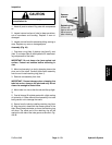
5. Start engine and allow coring head to fully raise. Turn
engine off. Secure coring head with service latch.
CAUTION
sure in the General Information section of this
Operate all hydraulic controls to relieve system
pressure and avoid injury from pressurized hy-
draulic oil. See Relieving Hydraulic System Pres-
chapter.
6. Release hydraulic pressure in lift cylinder:
A. Turn key switch to ON (engine not running).
B. Move traction lever to forward direction and de-
press lower switch on handle to lower coring head
onto service latch.
7. Disconnect hydraulic hose from hydraulic fitting on
lift cylinder. Locate and discard o–ring from between
hose and fitting. Allow hose to drain into a suitable con-
tainer.
8. Plug disconnected hose and fitting to prevent con-
tamination.
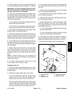
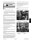
9. Remove one retaining ring from the upper cylinder
pin. Pull upper cylinder pin from the lift cylinder and cor-
ing head frame. Locate and retrieve spacer and thrust
washer from each side of cylinder pivot (Fig. 43).
10.Remove one retaining ring from the lower cylinder
pin on the side of the disconnected extension spring.
Support lift cylinder and slide lower cylinder pin from the
lift cylinder and machine frame.
11. Remove lift cylinder from the machine.
12.If needed, remove hydraulic fitting and o–ring from
the lift cylinder. Discard o–ring.
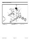
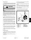
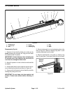
Installation (Fig. 41)
1. If removed, install hydraulic fitting and new o–ring
into lift cylinder.
2. Position lift cylinder to the machine mounting points.
Make sure the port of the lift cylinder faces the front of
the machine.
3. Align lower lift cylinder mounting hole with frame
mount. Install cylinder pin and secure with retaining ring.
4. Align upper lift cylinder pivot with slots in the coring
head frame. Install cylinder pin making sure that a
spacer is on each side of the cylinder pivot and a thrust
washer is positioned between coring head frame and re-
taining ring (Fig. 43). Secure with retaining ring.
5. Remove plugs from disconnected hose and fitting.
6. Connect hydraulic hose with new o–ring to hydraulic
fitting on lift cylinder. Tighten hose connection.
7. Install disconnected extension spring to machine in
reverse order of disassembly.
8. Install rear hood.
9. Install tine heads to stomper arms (see Operator’s
Manual).
10.Follow Hydraulic System Start–up procedures.
2
3
1
4
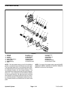
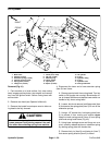
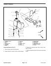
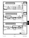
Figure 42
1. Extension spring 3. Lower carriage screw
2. Upper carriage screw 4. 1/2” drive hole
4
4
2
2
3
1
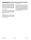
Figure 43
1. Lift cylinder shaft 3. Cylinder pin
2. Thrust washer 4. Spacer
Hydraulic
System
ProCore 648 Page 4 – 51 Hydraulic System