


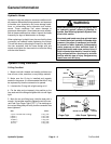

SAE Straight Thread O–Ring Port – Non–adjustable
1. Make sure both threads and sealing surfaces are
free of burrs, nicks, scratches, or any foreign material.
2. Always replace the O–ring seal when this type of fit-
ting shows signs of leakage.
3. Lubricate the O–ring with a light coating of oil.
O–Ring
4. Install the fitting into the port and tighten it down full
Figure 3
length until finger tight.
5. Tighten the fitting to the correct Flats From Finger
Tight (F.F.F.T.).
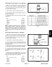
Size F.F.F.T.
4 (1/4 in. nominal hose or tubing) 1.00 +
0.25
6 (3/8 in.) 1.50 + 0.25
8 (1/2 in.) 1.50 + 0.25
10 (5/8 in.) 1.50 + 0.25
12 (3/4 in.) 1.50 +
0.25
16 (1 in.) 1.50 +
0.25
Fitting Size Installation Torque
4 9–10 ft–lb (12–13 N–m)
6 20–21 ft–lb (27–28 N–m)
8 35–37 ft–lb (47–50 N–m)
10 60–66 ft–lb (81–89 N–m)
12 81–87 ft–lb (110–117 N–m)
16 121–131 ft–lb (164–177 N–m)
NOTE: Installation torque values for non–adjustable fit-
Figure 4
tings are listed in Figure 4. These torque values should
only be used when a fitting can be accessed with a
socket. Use of an offset wrench (e.g. crowfoot wrench)
will affect torque wrench accuracy and should not be
used.
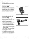
SAE Straight Thread O–Ring Port – Adjustable
1. Make sure both threads and sealing surfaces are
free of burrs, nicks, scratches, or any foreign material.
2. Always replace the O–ring seal when this type of fit-
ting shows signs of leakage.
3. Lubricate the O–ring with a light coating of oil.
4. Turn back the jam nut as far as possible. Make sure
Lock Nut
Back–up Washer
the back up washer is not loose and is pushed up as far
as possible (Step 1).
O–Ring
5. Install the fitting into the port and tighten finger tight
Figure 5
until the washer contacts the face of the port (Step 2).
6. To put the fitting in the desired position, unscrew it by
the required amount, but no more than one full turn
(Step 3).
Step 1
Step 4
Step 3
7. Hold the fitting in the desired position with a wrench
and turn the jam nut with another wrench to the correct
Flats From Finger Tight (F.F.F.T.) (Step 4).
Size F.F.F.T.
Step 2
4 (1/4 in. nominal hose or tubing) 1.00 + 0.25
6 (3/8 in.) 1.50 + 0.25
8 (1/2 in.) 1.50 + 0.25
10 (5/8 in.) 1.50 +
0.25
12 (3/4 in.) 1.50 +
0.25
16 (1 in.) 1.50 +
0.25
Figure 6
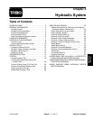
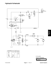
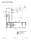
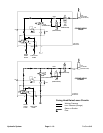
Hydraulic
System
ProCore 648 Page 4 – 5 Hydraulic System