


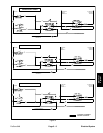
Component Testing
For accurate resistance and/or continuity checks, elec-
trically disconnect the component being tested from the
circuit (e.g. unplug the ignition switch connector before
doing a continuity check).
NOTE: Electrical troubleshooting of any 12 Volt power
connection can be performed through voltage drop tests
without disconnecting the component.
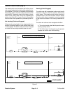
NOTE: See the Kohler Engine Service Manual for en-
gine component testing information.
CAUTION
ity with a multimeter (ohms setting), make sure
When testing electrical components for continu-
that power to the circuit has been disconnected.
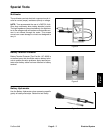
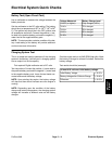
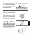
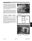
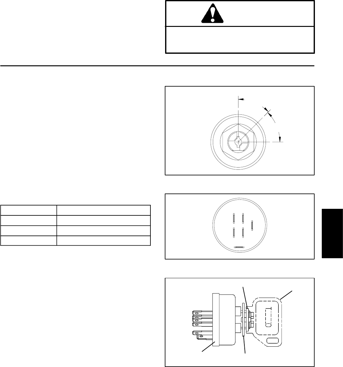
Ignition Switch
The ignition (key) switch has three positions (OFF, RUN,
OFF
and START) (Fig. 7). The terminals are marked as
shown in Figure 8.
Testing
The circuitry of the ignition switch is shown in the chart
below. With the use of a multimeter (ohms setting), the
45
45
RUN
o
o
START
switch functions may be tested to determine whether
continuity exists between the various terminals for each
switch position.
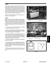
Unplug wire harness connectors from switch and verify
continuity between switch terminals. Reconnect the har-
Figure 7
ness connectors to the switch after testing.
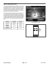
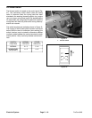
POSITION
CIRCUIT
OFF G + M + A
RUN B + L + A
START B + L + S
G
L
B
S
M
A
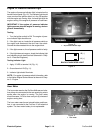
The Aerator Control Module monitors the operation of
the ignition switch. If the ignition switch is in the ON posi-
Figure 8
tion, the Module power input LED should be illuminated.
If the ignition switch is in the START position, the Module
start output LED should also be illuminated.
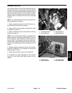
SWITCH
HEX NUT
KEY
LOCK WASHER
Electrical
System
Figure 9
ProCore 648
Page 5 – 13
Electrical System