


ProCore 648Hydraulic System Page 4 – 48
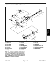
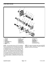
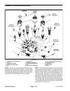
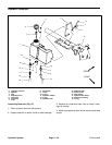
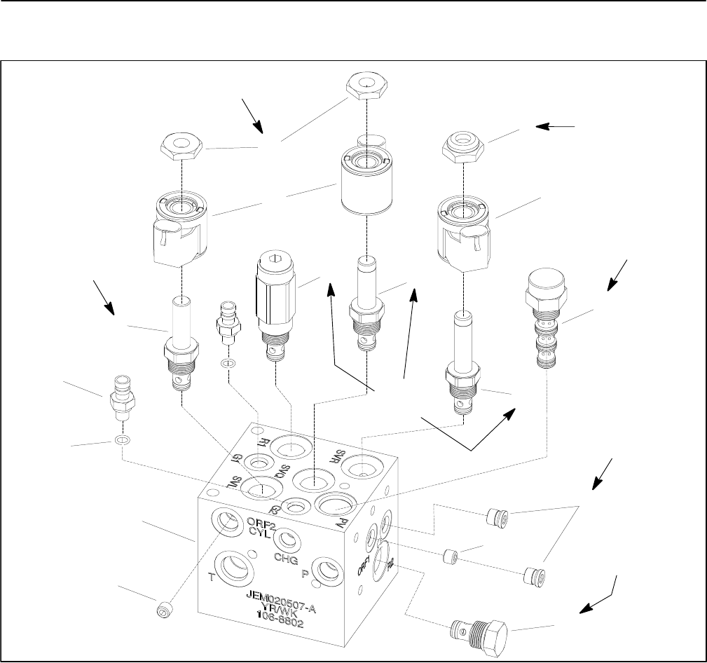
Hydraulic Lift Control Manifold Service
1. Hydraulic lift control manifold
2. O–ring
3. Quick fitting (2 used)
4. Solenoid valve (SVL port)
5. Nut
6. Solenoid coil
7. Relief valve (R1 port)
8. Solenoid valve (SVQ port)
9. Nut
10. Solenoid valve (SVR port)
11. Pres. compensating valve (PV port)
12. #4 plug (zero leak)
13. Orifice plug
14. Check valve
15. Plug
Figure 40
5
2
1
4
3
8
7
6
13
12
11
10
9
25 ft–lb
(33.9 N–m)
5 ft–lb
(6.8 N–m)
20 ft–lb
(27.1 N–m)
5 ft–lb
(6.8 N–m)
120 in–lb
(13.6 N–m)
20 ft–lb
(27.1 N–m)
20 ft–lb
(27.1 N–m)
6
14
15
NOTE: The ports on the manifold are marked for easy
identification of components. Example: P is the pump
connection port and R1 is the location for the relief valve
(See Hydraulic Schematics to identify the function of the
hydraulic lines and cartridge valves at each port).
NOTE: The ProCore 648 hydraulic lift control manifold
uses two zero leak plugs (item 12). These plugs have a
tapered sealing surface on the plug head that is de-
signed to resist vibration induced plug loosening. The
zero leak plugs also have an o–ring (not shown) as a
secondary seal. If zero leak plug removal is necessary,
lightly rap the plug head using a punch and hammer be-
fore using an allen wrench to remove the plug: the im-
pact will allow plug removal with less chance of damage
to the socket head of the plug. When installing plug,
torque 120 in–lb (13.6 N–m).