


ProCore 648 Page 7 – 17 Coring Head
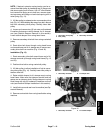
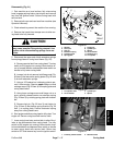
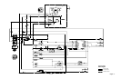
Disassembly (Fig. 21)
1. Park machine on a level surface, fully raise coring
head, engage parking brake, stop engine and remove
key from the ignition switch. Secure coring head with
service latch.
2. Remove belt cover and rear hood from machine (see
Operator’s Manual).
3. Chock wheels to prevent the machine from moving.
4. Remove tine heads from stomper arms to allow cor-
ing head to be fully lowered.
CAUTION
The extension springs are under tension and
may cause personal injury during removal. Use
caution when disconnecting springs from ma-
chine.
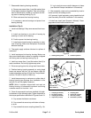
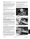
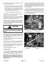
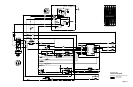
5. Disconnect the upper end of both extension springs
from spring plates on coring head frame (Fig. 22):
A. Remove service latch from coring head. Turn key
switch to ON (engine not running). Move traction le-
ver to forward direction and depress lower switch on
handle to fully lower coring head.
B. Loosen, but do not remove, both flange nuts (Fig.
22 item 6) that secure the spring plates (Fig. 22 item
5) for both extension springs.
C. Using a 1/2” breaker bar, hold spring plate to pre-
vent it from moving. Remove upper flange nut and
carriage screw (Fig. 22 item 4) from spring plate and
coring head frame.
D. Using lower carriage screw and flange nut as a
pivot, carefully release tension on extension spring
(Fig. 22 item 3) by rotating spring plate with breaker
bar.
E. Remove hair pin (Fig. 22 item 3) and clevis pin
(Fig. 22 item 2) that secure spring shackle (Fig. 22
item 1) to spring plate. Position extension spring
away from coring head frame.
6. Start engine and allow coring head to fully raise. Turn
engine off. Secure coring head with service latch.
7. Lower coring head onto service latch to allow lift cyl-
inder to be disconnected from coring head. Turn key
switch to ON (engine not running). Move traction lever
to forward direction and depress lower switch on handle
to lower coring head onto service latch. Return key
switch to OFF and remove key from the ignition switch.
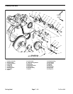
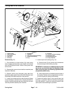
1. Shackle
2. Clevis pin
3. Hair pin
4. Extension spring
5. Carriage screw
6. Spring plate
7. Flange nut
8. Cylinder pin
9. Spacer
10. Thrust washer
11. Retaining ring
12. Lift cylinder
Figure 22
1
2
5
9
3
6
8
11
10
7
12
4
FRONT
RIGHT
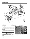
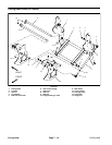
1. Lift cylinder shaft
2. Thrust washer
3. Cylinder pin
4. Spacer
Figure 23
4
4
2
2
3
1
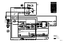
1. Proximity switch bracket 2. Machine frame
Figure 24
2
1
Coring Head