


Hydraulic System Start--up
NOTE: When initially starting the hydraulic system with
new or rebuilt components such as the hydraulic pump,
wheel motors or lift cylinder, it is important that this start
--
up procedure be used. This procedure reduces the
chance of damaging the hydraulic system or its c ompo
-
nents from not purging the system of air.
1. After the hydraulic system components have been
properly installed and if the hydraulic pump was rebuilt
or replaced, make sure traction pump housing is at least
half full of clean hydraulic oil (see Operator’s Manual for
oil s pecifications).
2. Make sure all hydraulic connections and lines are se-
cured tightly.
3. Make sure hydraulic reservoir is full. Add correct oil
if necessary (see Operator’s Manual). Drain, flush and
refill hydraulic system reservoir and change oil filter if
component failure was severe or if system is contami
-
nated.
4. After repairs, check control linkage for proper adjust-
ment, binding or broken parts. Correct any problems be-
fore proceeding.
5. Disconnect and ground both engine spark plug wires
to prevent engine from starting.
6. Make sure traction lever is in neutral. Turn ignition
key switch to start; engage starter for ten (10) seconds
to prime hydraulic pump. Repeat this step again.
7. Reattach both spark plug wires.
8. Apply parking brake and make sure traction lever is
in neutral. Start engine and run at low idle. The charge
pump should pick up oil and fill the hydraulic system.
9. If traction circuit was repaired (e.g. hydrostat or
wheel motor was replaced), bleed the traction circuit to
evacuate air from the circuit:
NOTE: Before bleeding the traction circuit, review the
following procedure (steps A through L) completely.
A. Stop engine and relieve pressure in traction cir-
cuit by moving traction lever to both forward and re-
verse direction.
B. Jack up machine from floor and support machine
with jack stands or blocking to allow wheels to turn
freely.
C. Attach a heavy chain between the rear of the ma-
chine frame and something immovable in the shop to
prevent the machine from moving during the bleed
-
ing process.
IMPORTANT: Make sure oil flow indicator arrow
on the flow gauge is showing that oil will flow
from the test port of traction line and through the
tester.
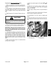
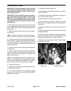
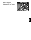
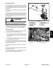
D. Connect inlet end of hydraulic tester with flow me-
ter and pressure gauges to test port in upper traction
line (Fig. 27). Place outlet end of tester in a drain con
-
tainer. Make sure that flow control valve on the tester
is fully closed.
E. Check hydraulic reservoir level and fill if neces-
sary.
F. Start engine and move traction lever to the for-
ward direction to allow the wheels to rotate slowly.
NOTE: Bleeding the traction circuit might require
approximately five (5) minutes of running.
IMPORTANT: When bleeding the traction circuit,
tester valve should be barely open which will al
-
low a slow stream of oil from tester outlet.
G. While traction lever is held in the forward direction
(wheels turning), have second person slowly open
valve on tester very slightly to allow air out of traction
circuit. Air in the traction circuit will be indicated by
foamy oil coming from the outlet end of the tester.
H. While bleeding the traction circuit, if more than .5
gallon (1.9 liters) of oil is removed, close tester valve
and release traction lever. Check hydraulic oil reser
-
voir level and fill if necessary. Continue with bleeding
procedure.
I. When all evidence of foamy oil has been evacuat-
ed from the traction circuit, close tester valve, re-
lease traction lever and stop engine.
J. Remove tester from traction circuit test port.
Check hydraulic reservoir level and fill if necessary.
K. If the hydrostat or a w heel motor was replaced or
rebuilt, start engine and operate the traction system
so the wheels rotate slowly for 10 minutes.
L. Lower machine to ground. Remove chain from
rear of machine.
Hydraulic System Page 4 -- 32
Rev. A
ProCore 648