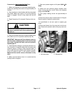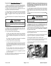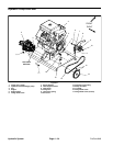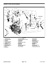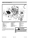
Drive Belt Removal (Fig. 27)
1. Park machine on a level surface, fully raise coring
head, engage parking brake, stop engine and remove
key from the ignition switch. Secure coring head with
service latch.
2. Remove pump belt cover from machine (see Opera-
tor’s Manual).
3. Remove coring head primary drive belt from electric
clutch (see Primary Drive Belt Removal in Service and
Repairs section of Chapter 7 – Coring Head).
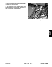
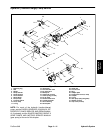
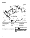
4. Loosen the flange head screw (item 6) and flange nut
(item 10) that secure the drive belt idler pulley (item 11).
Lift idler pulley to allow removal of drive belt from the pul-
leys and the machine.
Drive Belt Installation (Fig. 27)
1. Install pump drive belt to pulleys.
2. Lift idler pulley and insert pump drive belt under idler.
3. Allow tensioning spring to apply tension to idler
pulley. Tighten flange head screw (item 6) and flange nut
(item 10) to secure belt adjustment.
4. Install coring head primary drive belt to electric clutch
(see Primary Drive Belt Installation in Service and Re-
pairs section of Chapter 7 – Coring Head).
5. Install pump belt cover to machine (see Operator’s
Manual).
ProCore 648 Page 4 – 35 Hydraulic System
Hydraulic
System


