


ProCore 648 Hydraulic SystemPage 4 – 37
Disassembly (Fig. 28)
1. Park machine on a level surface, fully raise coring
head, engage parking brake, stop engine and remove
key from the ignition switch. Secure coring head with
service latch.
2. Remove pump belt cover from machine (see Opera-
tor’s Manual).
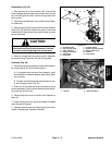
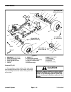
3. Remove two (2) lock nuts that secure pump shield to
pump (Fig. 29). Remove shield from pump. Locate and
retrieve two (2) flat washers from tops of studs on pump
control assembly.
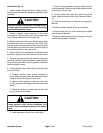
CAUTION
The extension spring is under tension and may
cause personal injury during removal. Use cau-
tion when removing spring from neutral lever.
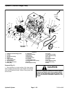
4. Remove components from pump control assembly
as needed using Figures 28, 29 and 30 as guides.
Assembly (Fig. 28)
1. Install removed components to pump control assem-
bly using Figures 28, 29 and 30 as guides.
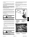
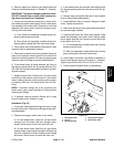
A. If rod ends were removed from damper, apply
Loctite #242 to threads of damper shaft before instal-
ling rod ends.
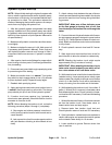
B. Damper should be secured to third hole from out-
er end of traction lever (Fig. 30).
2. Place two (2) flat washers to tops of studs on pump
control assembly. Position pump shield to pump and se-
cure with two (2) lock nuts.
3. Install pump belt cover to machine (see Operator’s
Manual).
4. Check traction drive for neutral and adjust if needed
(see Operator’s Manual).
5. Operate machine and verify hole spacing accuracy.
Adjust if needed (see Operator’s Manual).
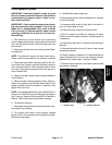
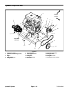
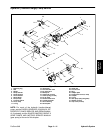
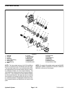
1. Hydraulic pump
2. Cap screw (2 used)
3. Control bracket
4. Flange nut (2 used)
5. Flat washer
6. Pump lever
7. Trunnion clamp
8. Socket hd screw (2 used)
9. Washer head screw
10. Lock nut
11. Pump shield
Figure 29
4
3
2
1
10
11
5
6
7
8
10
9
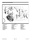
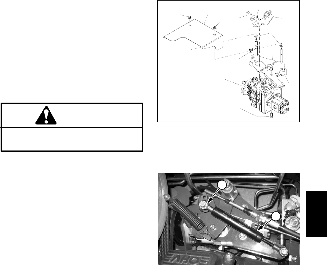
1. Damper 2. Rod end location
Figure 30
1
2
Hydraulic
System