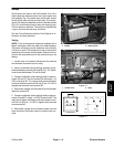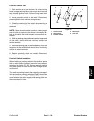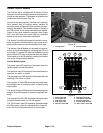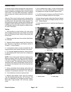
Proximity Switch Test
1. Park machine on a level surface, fully raise coring
head, engage parking brake, stop engine and remove
key from the ignition switch. Secure coring head with
service latch.
2. Locate proximity switch to be tested. Disconnect
proximity switch from machine wiring harness.
3. Check the continuity of the switch by connecting a
multimeter (ohms setting) across the switch connector
terminals.
NOTE: Before checking switch continuity, clean target
end of switch to make sure that there is no metallic de-
bris on the switch that could prevent correct switch op-
eration.
4. With the sensing plate positioned near the target end
of the switch, there should be continuity across the
switch terminals.
5. When the sensing plate is positioned away from the
target end of the switch, there should be no continuity
across the switch terminals.
6. Replace proximity switch as needed. Reconnect
switch to machine wiring harness.
Proximity Switch Installation
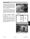
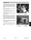
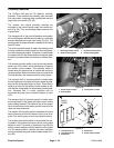
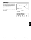
When installing a proximity switch to the machine, place
tab on switch plate into switch mounting hole nearest
target end of switch (Fig. 32). Secure proximity switch
and switch plate to switch mount with carriage screw
and lock nut.
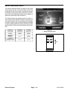
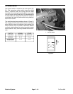
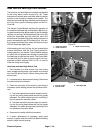
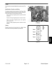
The switch mounting bracket that retains the transport
limit and aeration proximity switches (Fig. 30) should be
mounted to allow from .030” to .090” (.8 to 2.3 mm) clear-
ance between the switch targets and sensing plate on
the coring head H–frame.
3
2
1
4
5
Tab
Switch
Target
End
Figure 32
1. Carriage screw
4. Switch plate
2. Switch mount
5. Lock nut
3. Proximity switch
Electrical
System
ProCore 648
Page 5 – 23
Electrical System


