


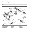
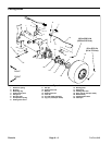
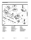
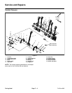
Disassembly (Fig. 7)
1. Park machine on a level surface, fully raise coring
head, engage parking brake, stop engine and remove
key from the ignition switch. Secure coring head with
service latch.
2. Block rear wheels. Jack front of machine from
ground and support machine with blocking or jack
stands (see Operator’s Manual and Jacking Instructions
in Chapter 1 – Safety).
3. Remove front wheel assembly (see Wheel Removal
in this section).
4. Remove front wheel motor (see Wheel Motor Re-
moval in Service and Repairs section of Chapter 4 – Hy-
draulic System).
5. Remove fuel tank from machine (see Fuel Tank Re-
moval in Service and Repairs section of Chapter 3 –
Kohler Engine).
6. Remove two (2) cap screws that secure cable guide
to steering arm. Position cables and wire harness away
from steering arm.
7. Support control handle. Remove three (3) lock nuts
that secure control handle to steering arm. Slide control
handle from steering arm taking care to not damage
control cables or wiring harness that will stay attached
to machine. Position handle away from steering arm.
8. Support steering arm. Remove cotter pin and slotted
hex nut from upper end of steering spindle. Lower steer-
ing arm from frame.
9. If necessary, remove steering spindle from steering
arm.
10.If necessary, remove control handle from machine:
A. Remove six (6) washer head screws that secure
lower handle cover to control handle. Remove lower
handle cover.
B. Remove four (4) screws that secure handle con-
trol cover to control handle. Unplug harness connec-
tors from low oil pressure light and raise lower switch
on cover.
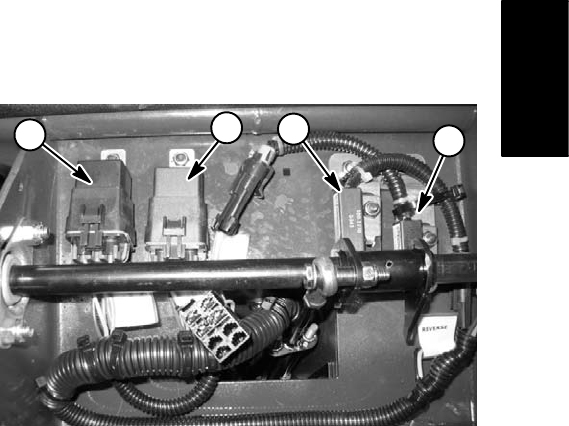
C. Unplug harness connectors from neutral relay,
latching relay, neutral proximity switch and reverse
proximity switch on control handle.
D. Disconnect parking brake cable from brake lever
(see Parking Brake Cable Removal in this section).
E. Remove lock nut and cap screw that secure trac-
tion control cable to control lever. Locate and retrieve
two (2) flat washers. Loosen jam nut that secures
parking brake cable to underside of control handle.
11. Inspect bearing cups and cones for wear or damage.
Replace worn or damaged components.
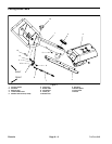
Assembly (Fig. 7)
1. If removed, secure steering spindle to steering arm
with four (4) cap screws.
2. If bearing cups were removed from frame, install new
cups to frame.
3. Install steering arm to frame:
A. Pack bearing cones with grease. Position lower
bearing on steering spindle shaft.
B. Slide steering shaft up through frame. Position
upper bearing and washer on steering spindle shaft.
C. Install slotted hex nut onto steering spindle, tight-
en completely and then back nut off slightly. Retigh-
ten nut until drag is felt while rotating steering arm.
Back–off nut to align spindle shaft hole with slotted
hex nut. Make sure that steering arm rotates freely
after slotted hex nut has been tightened.
D. Insert cotter pin through slotted hex nut and
steering spindle shaft.
4. Assemble steering components in the reverse order
of disassembly using Figure 7 as a guide.
5. Lower machine to ground. Remove service latch
from coring head before machine use.
6. Make sure that steering components do not contact
cables or wire harness.
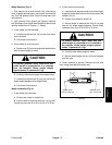
1
2
3
1
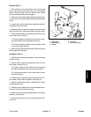
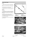
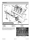
Figure 8
1. Relay 3. Neutral prox switch
2. Reverse prox switch
Chassis
ProCore 648 Page 6 – 11 Chassis