


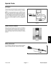
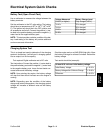
Relays
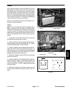
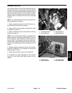
Six (6) relays are used on the ProCore 648. Four (4) of
these relays are attached under the control panel next
to the battery (Fig. 13): lockout relay, clutch relay, neutral
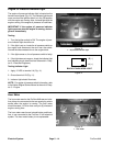
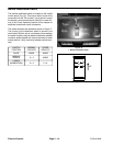
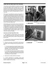
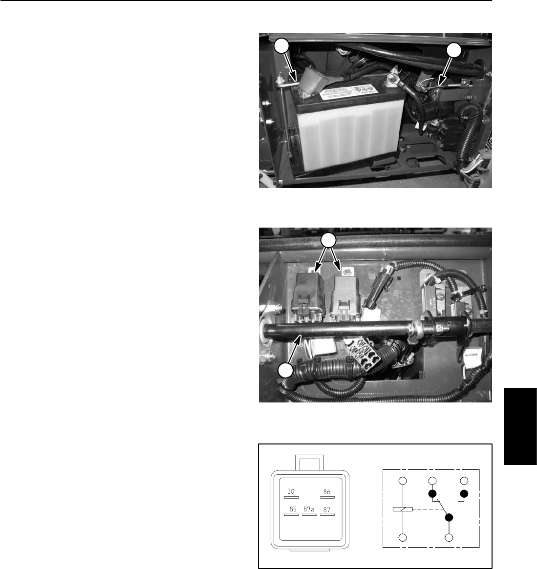
switch (start) relay and lockout latch relay. The remain-
ing two (2) relays are attached under the handle console
(Fig. 14): neutral switch (latch) relay and latching relay.
The six relays are identical. The relays are identified by
a tag on the wire harness relay connector.
See the Circuit Operation section of this Chapter for in-
formation on relay operation.
Testing
NOTE: Prior to taking small resistance readings with a
digital multimeter, short the meter test leads together.
The meter will display a small resistance value (usually
0.5 ohms or less). This resistance is due to the internal
resistance of the meter and test leads. Subtract this val-
ue from the measured value of the component you are
testing.
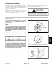
1. Locate relay to be tested. Disconnect the machine
wire harness connector from the relay.
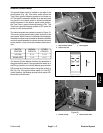
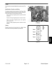
2. Using a multimeter (ohms setting), measure coil re-
sistance between terminals 85 and 86 (Fig. 15). Resist-
ance should be between 70 and 90 ohms.
3. Connect multimeter (ohms setting) leads to relay ter-
minals 30 and 87. Ground terminal 86 and apply +12
VDC to terminal 85. The relay should make and break
continuity between terminals 30 and 87 as +12 VDC is
applied and removed from terminal 85.
4. Disconnect voltage from terminal 85 and multimeter
lead from terminal 87.
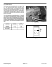
5. Connect multimeter (ohms setting) leads to relay ter-
minals 30 and 87A. Apply +12 VDC to terminal 85. The
relay should make and break continuity between termi-
nals 30 and 87A as +12 VDC is applied and removed
from terminal 85.
6. Disconnect voltage and multimeter leads from the
relay terminals. Reconnect relay to machine wire har-
ness.
2
1
Figure 13
1. Battery 2. Relay location
1
2
Figure 14
1. Traction lever
2. Relay
86
85
87A 87
30
Figure 15
Electrical
System
ProCore 648
Page 5 – 15
Electrical System