Front Panel Operations
Additional Features
2
2-33
totAL
SHIFT
TOTAL
TOTAL
TOTAL
XXXXX
totAL
TOTAL
TOTAL
XXXXX
totAL
0
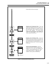
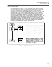
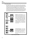
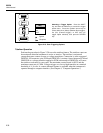
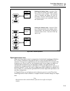
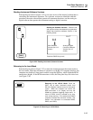
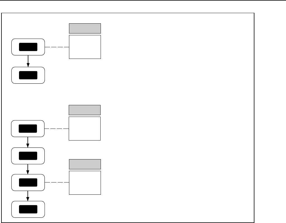
Reading the Totalizer Count. Press the TOTAL
key to view the contents of the totalizer counter.
The maximum count is 65535. If the maximum
count is exceeded, the display will show OL
(Overload). Press the TOTAL key again to exit.
To reset the counter to zero, see below, Erasing
the Totalizer Count.
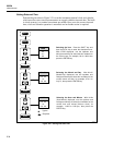
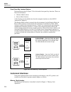
Erasing the Totalizer Count. Press the TOTAL
key to view the contents of the totalizer counter.
Press the SHIFT key and then the TOTAL key to
reset the counter to zero. Press the TOTAL key
again to exit.
op32f.eps
Figure 2-20. Totalizer Operation
Digital Input/output Lines
There are no front panel controls or annunciators for the digital input/output (I/O) lines,
I/O 7 to I/O 0. Connection to the eight I/O lines is via the rear panel DIGITAL I/O
connector. If a logic low is applied to any line, the instrument treats it as an input; if the
instrument sets a line to logic low, the instrument treats it as an output. An output low
condition takes precedence over an input high condition. All digital I/O lines are
controlled by a computer interface (see Chapter 4, "Computer Operations"); however, as
a default, lines I/O 7 to I/O 4 are used to output alarm status conditions for channels 4 to
20 (see Table 2-5). An instrument-generated I/O line alarm output takes precedence over
any other configuration.
All Digital I/O lines are set high (non-active) whenever power is cycled. These lines
remain high until an alarm condition or computer interface command changes an output
state.
Note
Measurements taken with the Monitor function do not affect the digital
outputs.


