


2635A
Users Manual
7-8
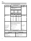
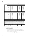
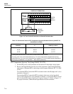
Table 7-3. Performance Tests (Voltage, Resistance, and Frequency) (cont)
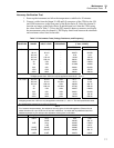
Using inputs in decades of 1.9:
300 e short 0.00 0.09
190 e 189.93 190.12
3 ke short 0.0000 0.0003
1.9 ke 1.8992 1.9008
30 ke 19 ke 18.992 19.008
300 ke 190 ke 189.91 190.09
3 Me 1.9 Me 1.8983 1.9017
Using inputs in decades of 1:
300 e short 0.00 0.09
100 e 99.95 100.10
3 ke short 0.0000 0.0003
1 ke 0.9995 1.0006
30 ke 10 ke 9.995 10.005
300 ke 100 ke 99.94 100.06
3 Me 1 Me 0.9990 1.0010
10 Me* 10 Me 9.979 10.021
*Optional test point if standards available.
NOTE
All channels (0 through 20) can accommodate 2-terminal resistance measurements. Channel 0, with
only two connections, cannot be used for 4-terminal measurements. Four-terminal resistance
measurements can be defined for channels 1 through 10 only. Channels 11 through 20 are used, as
required, for 4-terminal to provide the additional two connections. For example, a 4-terminal set up on
channel 1 uses channels 1 and 11, each channel providing two connections.
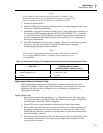
Frequency 90 kHz/2V
p-p
10kHz 9.994 10.006
Channel Integrity Test
Ensure that the Accuracy Verification Test for channel 0 meets minimum acceptable
levels before performing this test.
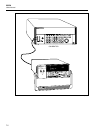
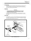
1. Switch OFF power to the instrument and disconnect all high voltage inputs.
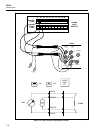
2. Remove the Input Module from the rear of the instrument. Open the Input Module
and connect a pair of test leads to the H (high) and L (low) terminals of channel 1.
Reinstall the Input Module into the instrument.
3. Connect the ends of the test leads together to apply a short (0 ohms).
4. Reconnect power and switch the instrument ON.