


2635A
Users Manual
2-20
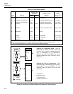
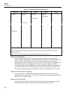
Table 2-4. TLL Alarm Outputs (Channels 0 to 3)
Channel 3 Channel 2 Channel 1 Channel 0 Decimal
0 (Alarm) 0 (Alarm) 0 (Alarm) 0 (Alarm) 0
0001 (No Alarm)1
001 (No Alarm)02
00113
01 (No Alarm)004
01015
01106
01117
1(No Alarm)0008
10019
101010
101111
110012
110113
111014
111115
1 = No Alarm 0 = Alarm
Note 1. The decimal equivalent of the binary half-byte formed by Channel 3 to Channel 0 is used in
autoprint functions.
Note 2. The TTL alarm outputs are via the ALARM OUTPUTS rear panel connector.
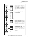
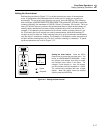
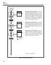
Alarms and Autoprinting
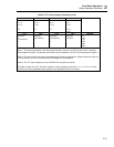
Alarm conditions are indicated for each scanned channel when using the autoprint
function, and the ALM (Alarm) and DIO (Digital I/O) conditions are summarized with a
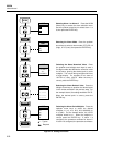
decimal number. (See Tables 2-4 and 2-5.)An alarm condition can be used to turn
autoprinting on and off by selecting "Print" (printer) or "both" (printer and memory card)
as a data destination, and the data mode as ALAr (Alarm) (see Figure 5-3). When
scanning using the front panel Q key, the printer will print measurement results when
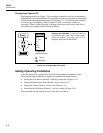
any scanned channel is in alarm. If scanning using the alarm trigger (see Figure 2-19),
the printer will print measurement results only when the monitored channel is in alarm.
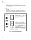
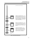
Alarms and Monitor-Alarm Triggering
An alarm condition, coupled with the Monitor Mode, can be used to start and stop
measurement scans (see Figure 2-19). When an alarm occurs, scanning begins, and when
the alarm clears, scanning stops.
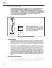
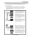
Alarms and Mx+B Scaling
Alarm settings are affected by Mx+B scaling. The Mx+B scaling determines the value
that the instrument displays, and the alarms are configured for these values.