Front Panel Operations
Setting Operating Conditions
2
2-19
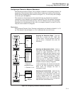
Alarm Indications While Monitoring
If the channel being monitored is in an alarm condition, the alarm limit 1 and/or 2
annunciators will be turned on, and the ALARM annunciator blinks bright/dim. The
alarm limit annunciator indicates which alarm has been exceeded. If the monitored
channel is not in alarm, the ALARM annunciator will be off, unless scanning and some
other channel is in alarm, then the ALARM indicator has a steady dim display. See
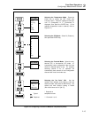
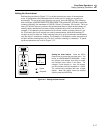
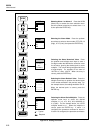
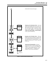
Figure 2-17 for information about the Monitor Mode.
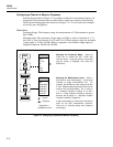
Alarm Indications While Reviewing
If the channel being reviewed had been in an alarm condition, the ALARM and alarm
limit 1 and/or 2 annunciators will be turned on. The alarm limit annunciator indicates
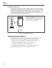
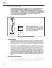
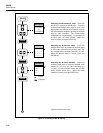
which alarm has been exceeded. See Figure 2-18 for information about the Review
Mode.
Clearing Alarm Parameters from a Channel
To clear alarm parameters from a channel, the alarm can be programmed to OFF for both
alarm 1 and alarm 2, or the channel function can be changed to any other selection,
including OFF.
Alarm Outputs for Channel 0 to 3 Using the Alarm Outputs Connector
A dedicated transistor-transistor logic (TTL) voltage output is available for channel 0 to
channel 3 alarms, via the rear panel ALARM OUTPUTS connector. (See Chapter 1 of
this manual for connection information.)If a channel is not in alarm, the voltage output at
a connector terminal is a logical high (nominal +5V dc); if a channel is in alarm, the
output is a logical low (nominal +0.7V dc). Alarm outputs are set following each scan.
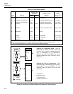
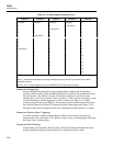
As shown in Table 2-4, there are 16 different alarm combinations. The decimal
equivalent of the binary half-byte formed by Channel 3 to Channel 0 has significance in
autoprinting operations. (See the following discussion on autoprinting.)
Alarm Outputs for Channels 4 to 20 Using the Digital I/O Connector
A shared transistor-transistor logic (TTL) voltage output is available for channel 4 to
channel 20 alarms via the rear panel DIGITAL I/O connector, using terminals I/O 7 to
I/O 4. (See Chapter 1 of this manual for connection information.)If a channel is not in
alarm, the voltage output at a connector terminal is a logical high (nominal +5V dc); if a
channel is in alarm, the output is a logical low (nominal +0.7V dc). Alarm outputs are set
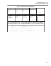
following each scan. As shown in Table 2-5, the alarm outputs for channels 4 to 20 are
ORed in groups. For example, a logical low at I/O 7 indicates that channel 7 or 11 or 15
or 19 is in an alarm condition. Dedicated alarm channels are available only for channels
0 to 3 (see the above). Assigning alarms to channels 4 to 20 does not disable the
associated I/O output from use by commands from the computer interface. (See using the
"Digital Input/Output Lines" under "Additional Features.") The decimal equivalent of
the binary byte formed by I/O 7 to I/O 0 has significance in autoprinting operations (see
the following discussion) and for certain commands in the instrument command set, e.g.,
LOG?.


