


Preparation for Use
Measurement Connections
1
1-17
Alarm Outputs Connections
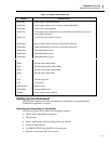
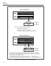
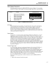
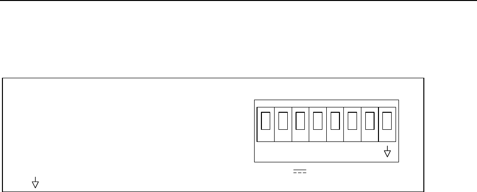
The eight-terminal rear panel ALARM OUTPUTS connector (Figure 1-7) serves three
functions: DC power, alarm outputs, and external trigger input. Each is described below.
9-16 V
DC PWR
ALARM OUTPUTS
+–
0123TR
Terminal
+
–
0
1
2
3
TR
Function
Positive Input for DC Operation
Negative Input for DC Operation
Channel 0 Alarm Output
Channel 1 Alarm Output
Channel 2 Alarm Output
Channel 3 Alarm Output
External Trigger Input
Ground Terminal
op07f.eps
Figure 1-7. ALARM OUTPUTS connector
DC Power
The instrument may be powered by a dc input between 9 volts and 16 volts allowing
remote operation from various battery sources or dc power supplies. Connect the
positive lead of the power supply to the + terminal and the negative lead to the -
terminal. If the instrument is going to measure voltages greater than 50 volts dc or ac
rms, also connect a ground wire between the rear panel ground lug and a suitable earth
(safety) ground point (see Figure 1-4).
Alarm Outputs
Terminals 0, 1, 2, and 3 are used to signal alarm conditions for channels 0, 1, 2, and 3
respectively using transistor-transistor-logic (TTL) voltage levels, referenced to the
GROUND terminal. Logic high is >+2.0 to <+5.5V dc; a logic low is 0.0 to +0.8V dc. If
a channel is not in alarm, the voltage output at a connector terminal is a logical high
(nominal +5V dc); if a channel is in alarm, the output is a logical low (nominal +0.7V
dc). Alarm outputs are set at the end of a scan interval. See Setting the Alarms in
Chapter 2 for more information. If the instrument is operated over the RS-232 computer
interface, the ALARM OUTPUTS can be assigned to I/O functions (assuming channels
0, 1, 2, and 3 are not configured for alarms). See the ALARM_DO_LEVEL command,
described in Chapter 4.
External Trigger Input
An external trigger input can serve the same function as the front panel SCAN key. A
contact closure between TR and GROUND or a TTL logical low applied to TR
(referenced to GROUND), will cause the instrument to scan. When the trigger input is
removed, scanning will stop. Scanning is initiated on the falling edge of the trigger
signal, which must be held logic low for at least 5 us and have been preceded by at least
100 ms of logic high. Logic high is +2.0 to +7.0V dc; a logic low is -0.6 to +0.8V dc.
See "Scan Triggering Options" in Chapter 2 for more information.
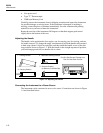
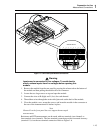
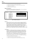
Perform the following procedure to make connections to the ALARM OUTPUTS
connector:
1. Remove the connector from the rear panel.