


2635A
Users Manual
1-6
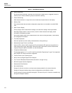
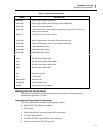
Table 1-1. Data Bucket Features
• Channel Scanning
Can be continuous scanning, scanning at an interval time, single scans, or triggered (internal or
external) scans. Channel Monitoring may be used while scanning.
• Channel Monitoring
Make measurements on a single channel and view these measurements on the display.
• Memory Card
Store measurement data and meter configuration setup data on a removable nonvolatile RAM
card.
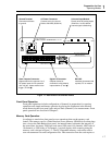
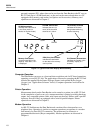
• Multi-Function Display
Primary display shows measurement readings; also used when setting numeric parameters.
Secondary display used for numeric entries, channel number selection and display, status
information, and operator prompts.
Annunciator display used to show measurement units, alarms review parameters, remote status,
and configuration information.
• Front-Panel Operation
Almost all operations can be readily controlled with the front panel keys.
• Measurement Input Function and Range
Volts dc (VDC), volts ac (VAC), frequency (HZ), and resistance (e) inputs can be specified in a
fixed measurement range. Autoranging, which allows the instruments to use the measurement
range providing the optimum resolution, can also be selected.
• Temperature Measurement
Thermocouple types J, K, E, T, N, R, S and B, and Hoskins Engineering Co. type C are supported.
Also, DIN/IEC 751 Platinum RTDs are supported.
• Totalize Events on the Totalizing Input
• Alarm Limits and Digital Output Alarm Indication
• Four-Terminal Resistance Measurements (Channels 1 through 10 only)
• RS-232 Computer Interface Operation
• Measurement Rate Selection
• Nonvolatile Memory
Storage of minimum, maximum, and most recent measurements for all scanned channels.
Storage of Computer Interface setup, channel configurations, and calibration values.
Internal storage of measurement data: storage for 100 scans of up to 21 channels, accessible only
through the computer interface.