


Preparation for Use
Controls and Indicators
1
1-19
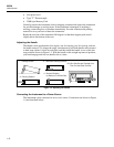
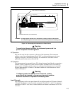
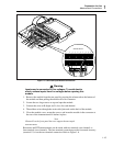
4. Tighten the wire clamp screw.
5. Insert the connector in the rear panel.
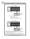
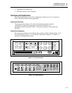
Controls and Indicators
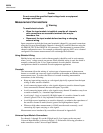
The front panel (Figure 1-1) provides a multipurpose display and a set of control keys.
Each is described in the following paragraphs.
Front Panel Controls
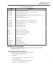
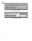
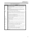
The front panel keys (Figure 1-9) control all instrument operation: channel
configuration, instrument configuration, measurement functions, and
print/communications selections. Table 1-3 provides a summary of front panel key
functions.
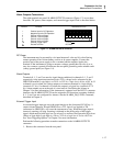
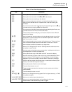
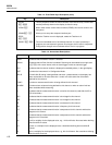
Front Panel Indicators
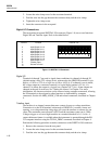
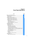
The front panel indicators are divided into three portions: Primary Display (Figure 1-10),
Secondary Display (Figure 1-11), and Display Annunciators (Figure 1-12). Table 1-4
describes each annunciator function.
CLOCK CLEAR
LOCAL COMM ZERO
RATE
MODE
SINGLE
TRIGS
FUNC ALRM
INTVL FILES REVIEW
SCAN
CANCL
ENTER
SHIFT LIST TOTAL
MONMx B
+
BUSY BATT
op09f.eps
Figure 1-9. Front Panel Keys
REVIEW
LAST
MAX
MIN
REM
AUTO
SCAN
MON
x1Mk
LIMIT
HI
LO
OFF
CAL
PRN
EXT
SET
Mx+B
FUNC
ALARM
°C °F RO
mV AC DC
Hz
CH
TR
12
Ω
F
op10f.eps
Figure 1-10. Primary Display