


2635A
Users Manual
x
2-24. Front Panel Key Lockout Options......................................................................... 2-36
3-1. Typical Memory Card............................................................................................ 3-3
3-2. Front Panel Memory Card Percent Display........................................................... 3-5
3-3. Initializing a Memory Card.................................................................................... 3-7
3-4. Recording Measurement Results During Scanning............................................... 3-8
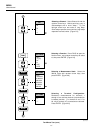
3-5. Using SETUP STORE to Save Configuration Files.............................................. 3-9
3-6. Using SETUP LOAD to Load Configuration Files............................................... 3-10
3-7. Using SETUP ERASE to Delete Configuration Files ........................................... 3-11
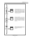
3-8. Using DATA OPEN to Save Measurement Data in a File.................................... 3-12
3-9. Using DATA ERASE to Delete a Measurement Data File ................................... 3-13
3-10. Using DIRECTORY to Examine SETUP and DATA files................................... 3-14
3-11. Using STATUS to Examine SETUP and DATA Files.......................................... 3-15
4-1. Connecting the Instrument to a PC........................................................................ 4-4
4-2. Configuring the Instrument for Computer Operations .......................................... 4-5
4-3. Overview of Status and Event Data Registers....................................................... 4-15
4-4. Sample Program (GWBASIC)............................................................................... 4-57
4-5. Sample Program (QBASIC)................................................................................... 4-59
4-6. Sample Program (QuickC) (1of 5)......................................................................... 4-62
5-1. Connecting the Instrument to a Printer.................................................................. 5-4
5-2. Configuring the RS-232 Ports for Print Operations .............................................. 5-5
5-3. Printing Measurement Results During Scanning................................................... 5-7
5-4. Printing the Review Array..................................................................................... 5-8
5-5. Printing the Memory Card Directory..................................................................... 5-10
6-1. Overall PC-to-Instrument Modem Connection...................................................... 6-3
6-2. Connecting the Modem to a PC............................................................................. 6-5
6-3. Connecting the Modem to an Instrument .............................................................. 6-6
6-4. Configuring the Instrument RS-232 Port for Modem Operations ......................... 6-7
7-1. Replacing the Line Fuse ........................................................................................ 7-3
7-2. Four-Terminal Connections to 5700A................................................................... 7-12
7-3. Four-Terminal Connections to Decade Resistance Box........................................ 7-14
7-4. Dedicated Alarms Output Test .............................................................................. 7-20
7-5. External Trigger Test............................................................................................. 7-21
C-1. ASCII String Decoding.......................................................................................... C-3
C-2. Floating_Point Conversion.................................................................................... C-6
C-3. Example ................................................................................................................. C-8
D-1. Summary of RS-232 Connections ......................................................................... D-3
D-2. Hydra Series II (DB-9) to PC (DB-9) RS-232 Connection (Generic)................... D-4
D-3. Hydra (DB-9) to PC (DB-25) RS-232 Connection................................................ D-5
D-4. Hydra Series II (DB-9 to Modem (DB-25) RS-232 Connection ........................... D-6
D-5. Hydra Series II (DB-9) to Printer (DB-25) RS-232 Connection ........................... D-7
D-6. RS-232 DB-9 and DB-25 Connectors.................................................................... D-8
G-1. Comparison of Common Waveforms .................................................................... G-2