


Preparation for Use
Measurement Connections
1
1-15
LH
L
H
L
H
H
L
H
L
H
L
H
L
H
L
H
L
H
L
HL
L
H
L
H
HL
H
L
H
L
H
L
H
L
H
L
H
L
HL
HL HLHLHLHLHL HLHLHL
HL HLHLHLHLHLHLHLHLHL
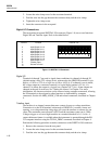
STRAIN RELIEF
1
11
2
12
3
13
4
14
5
15
6
16
7
17
8
18
9
19
10
20
op05f.eps
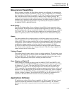
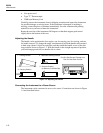
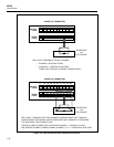
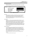
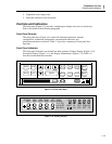
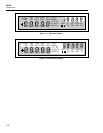
Figure 1-5. Universal Input Module Connections
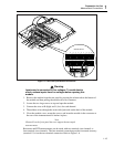
Warning
Inputs may be connected to live voltages. To avoid electric
shock, remove inputs from live voltages before opening this
module.
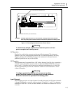
1. Remove the module from the rear panel by pressing the release tab on the bottom of
the module and then pulling the module out of its connector.
2. Loosen the two large screws on top and open the module
3. Connect the wires to H (high) and L (low) for each channel.
4. Thread these wires through the strain-relief pins and out the back of the module.
5. Close the module cover, secure the screws, and insert the module in the connector at
the rear of the instrument until it latches in place.
Note
Channel 0 on the front panel does not support thermocouple
measurements.
Resistance and RTD measurements can be made with two terminals (one channel) or
four terminals (two channels). The four-terminal connection provides increased accuracy
(nominal 1%) over the two-terminal connection. Refer to Figure 1-6.