


Maintenance
Performance Tests
7
7-9
5. For channel 1, select the two-terminal ohms function and 300 ohms range on the
Hydra Series II. Press M and ensure the display reads a resistance of less than or
equal to 4.0 ohms. (This test assumes that lead wire resistances are less than 0.1Ω.)
6. Open the ends of the test leads and ensure that the display reads OL" (overload).
7. Press M.This will stop the measurement.
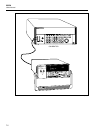
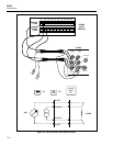
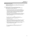
8. Connect a cable from the Output VA HI and LO of the 5700A to the Input Module
test leads (observe proper polarity).
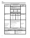
9. Select the VDC function and 300 volt range on the Hydra Series II and first apply
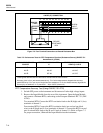
0V dc then 290V dc input from the 5700A. Ensure the display reads between the
minimum and maximum values as shown in Table 7-3 for the 0 and 290V dc input
levels.
Note
Channels 0, 1, and 11 have a maximum input of 300V dc or ac (rms). The
maximum input for all other channels is 150V dc or ac (rms).
10. With the exception of the selected voltage range and input voltage from the 5700A,
repeat steps 1 through 9 for each remaining Input Module channel (2 through 20).
Channels 2 through 10 and 12 through 20 should be configured for the 150V dc
range and an input voltage of 150 volts.
Thermocouple Measurement Range Accuracy Test
Ensure that the Accuracy Verification Test for channel 0 meets minimum acceptable
levels before performing this test.
Thermocouple temperature measurements are accomplished using Hydra Series II’s 90
mV and internal 900 mV dc ranges. (The 900 mV range is not configurable from the
instrument front panel.) This procedure will provide the means to test these ranges.
Testing the 900 mV dc range requires computer interfacing with a host (terminal or
computer). The host must send commands to select this range. This range cannot be
selected from the Hydra Series II front panel.
1. Ensure that communication parameters ( i.e., transmission mode, baud rate, parity,
CTS, and echo mode) on the Hydra Series II and the host are properly configured to
send and receive serial data. Refer to Chapter 4 "Computer Operations."
2. Power up Hydra Series II and allow the temperature to stabilize for 30 minutes.
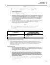
3. Connect a cable from the Output VA HI and LO connectors of the 5700A to the VΩ
and COM connectors on the front panel of the Hydra Series II.
4. Set the 5700A to output 0V dc.
5. Using either a terminal or a computer running a terminal emulation program as the
selected host, send the following commands to Hydra Series II:
FUNC 0,VDC,5 <CR>
MON 1,0 <CR>
MON_VAL? <CR>
The returned value for channel 0 should be 0 mV ±0.006 mV.
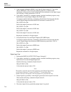
Set the 5700A to output 90 mV DC. Send the following command:
MON_VAL? <CR>