


Preparation for Use
Operating Modes
1
1-7
COMPLIES WITHFCC-15B
+–0123TR 01234567Σ
9-16 V
DC PWR
!
+30V
90-264V
50/60 Hz
15VA
CAUTION
FOR FIRE PROTECTION
REPLACE WITH T 1/8A 250V (SLOW) FUSE
ALARM OUTPUTS DIGITAL I/O
MEETS Vfg. 243/1991
RS-232C
GND
DTR
TX
RX
IEEE STD-488 PORT
SH1, AH1, T5, L4, SR1, RL1, DC1, DT1, PP0, C0, E1
IEC 664 INSTALLATIONCATEGORY II
2620A 2625A 2635AMODEL:
+–0123TR
[CTS]
[DSR]
[RTS]
01234567Σ
6789
54321
[2635A ONLY]
!
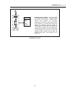
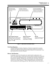
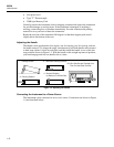
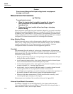
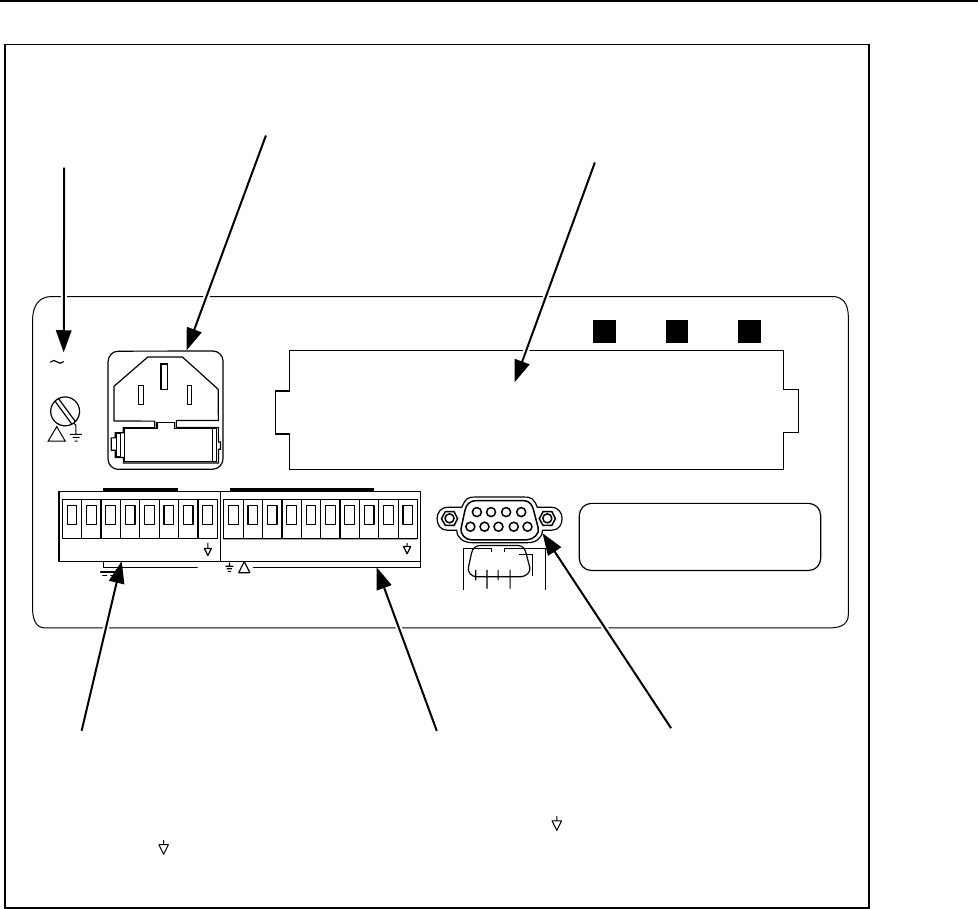
Ground Terminal.
Connects mainframe
to ground.
AC Power Connector.
Connect to any line source
of 90 to 264 VAC (50/60 Hz).
Universal Input Module.
Directly wires 20 analog inputs
(Channels 1 to 20) without
external signal conditioning.
Alarm Outputs Connector.
Outputs alarms for channels 0 to 3,
DC power inputs for DC operation
(9 to 16V dc), inputs external scan
trigger (TR and ).
Digital I/O Connector.
Outputs alarms for
channels 4 to 20 (default),
inputs totalizer (
Σ and ).
RS-232C.
Interfaces instrument with
a printer, PC or modem.
op01f.eps
Figure 1-1. Data Bucket Front and Rear Panels
Front Panel Operation
Front panel operations include configuration of channels in preparation for scanning
operations and simple multimeter operation by placing the instrument in the Monitor
mode then using the front panel jacks and test leads (channel 0) for measurements. Front
panel operations are discussed in Chapter 2.
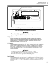
Memory Card Operation
An adjunct to stand-alone front panel use are operations that use the memory card
feature. The memory card is a Static Random Access Memory (SRAM) device that plugs
into a slot on the Data Bucket front panel. An internal battery maintains the integrity of
the stored data. An empty 256K-byte card stores 8500 scans of 4 channels, 4500 scans of
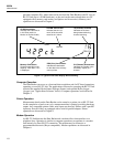
10 channels, or 2500 scans of 20 channels. A typical display while scanning using the
memory card is shown in Figure 1-2. The PC-compatible memory card can be used to
store measurement files and configuration files. Data extraction from the card requires a