


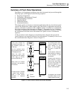
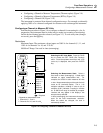
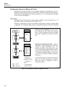
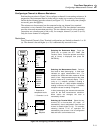
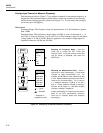

Front Panel Operations
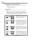
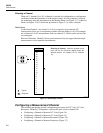
Configuring the Instrument for Operation
2
2-7
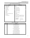
Table 2-1. Configuration Reset (Default) Settings
Parameter Default Setting
Channels 0 to 20 Off
Measurement Rate Slow
Mx+B Scaling 1x+0 (all channels)
Scan Interval 0:00:00 (continuous)
Review Values Cleared (all channels)
Digital I/O Lines Set High (non-alarm)
Totalizer 0/Debounce Disabled
Destination None
RTD R0 100.00 (all channels)
Open Thermocouple Detection (OTC) Enabled
Alarm Limits Off/Limit Values=0
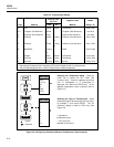
Alarm Assignments Channels 0 to 3, to ALARM OUTPUTS 0 to 3.
Channels 4 to 20, to DIGITAL I/O as below:
DIGITAL I/O LINE 4567
Alarm Channel 4567
(ORed to drive 8 9 10 11
each I/O line) 12 13 14 15
16 17 18 19
20
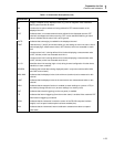
Table 2-2. Selftest Error Codes
Code Description
1 Boot ROM Checksum Error
2 Instrument ROM Checksum Error
3 Internal RAM Test Failed
5 Display Power-Up Test Failed
6 Display Not Responding
7 Instrument Configuration Corrupted
8 Instrument Not Calibrated
9 A-to-D Converter Not Responding
A A-to-D Converter ROM Test Failed
b A-to-D Converter RAM Test Failed
C A-to-D Converter Selftest Failure
d Memory Card Interface Not Installed