Front Panel Operations
Setting Operating Conditions
2
2-21
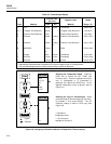
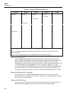
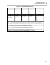
Table 2-5. TTL Alarm Outputs (Channels 4 to 20)
Channels Channels Channels Channels
7 -or- 6 -or- 5 -or- 4 -or-
11 -or- 10 -or- 9 -or- 8 -or-
15 -or- 14 -or- 13 -or- 12 -or-
19 18 17 16 -or-
20 -or-
I/O 7 I/O 6 I/O 5 I/O 4 Decimal
0 (Alarm) 0 (Alarm) 0 (Alarm) 0 (Alarm) 31
0 1 (No Alarm) 1 (No Alarm) 1 (Alarm) 127
1 (No Alarm) 0 1 1 191
1101223
1110239
1111255
1 = No Alarm 0 = Alarm
Note 1. The decimal equivalent of the binary byte formed by Channel 4 to Channel 20 is used in autoprint
and computer functions. The decimal values shown here are based on I/O 3 to I/O 0 being equal to logical 1.
Note 2. The above shows the least complicated Digital I/O alarm configurations. Multiple alarms plus the use
of I/O terminals 3 to 0 can conceivably use all 255 digital I/O combinations.
Note 3. The TTL alarm outputs are via the DIGITAL I/O rear-panel connector
Example: A logical 0 at I/O 7 terminals indicates an alarm condition for channel 7, or 11, or 15, or 19. Only
channels 0 to 3 have dedicated alarm outputs on the ALARM OUTPUTS connector.


