


2635A
Users Manual
4-14
Positive overload (OL on display) returns +001.00E+9
Negative overload (-OL on display) returns -001.00E+9
Open thermocouple (otc on display) returns +009.00E+9
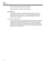
Status Registers
Internal instrument operation is summarized in three data registers, which can be
accessed to determine various events and status conditions before, during, and after
instrument operation. Each register has a corresponding enable register to enable or
mask (disable) any or all data register outputs. The relationship between the three
registers is shown in Figure 4-3.
Instrument Event Register (IER)
The inputs to the Instrument Event Register (IER) include Scan Complete, Configuration
Corrupted, Calibration Corrupted, Open Thermocouple, Totalize Overflow, and Alarm
Limit Transition. Each input is described in Table 4-1. The output byte of the IER is
ANDed with the output byte of the corresponding Instrument Event Enable Register
(IEE). When there is logic high correlation between any of the bits of the IER and IEE
registers, the associated Logical OR gate will output a logic high to the Instrument Event
Bit (IEB) in the Status Byte Register.