


Computer Operations
Computer Interface Commands and Operation
4
4-17
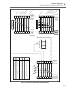
associated Logical OR gate will output a logic high to the Event Status Bit (ESB) in the
Status Byte Register.
For example, an ESR byte of binary 00010000 (decimal 16) indicates an Execution
Error. If the ESE register is set to binary 00010000 (using the command *ESE 16), then
an Execution Error condition will cause the Logical OR gate to output a logic high. In a
similar manner, parameters can be combined. An ESR byte of binary 00110000 (decimal
48) and an ESE set to a corresponding binary 00110000 (using the command *ESE 48),
will cause the Logical OR gate to have a logic high output for any of two conditions:
Command Error or Execution Error.
Other commands include *ESR?, which returns the decimal equivalent of the ESR byte
and then clears the register to zero, and *ESE?, which returns the decimal equivalent of
the ESE byte. The command *CLS will clear all event registers. (See Appendix E for an
8-bit binary-coded decimal table.)
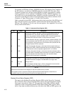
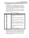
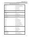
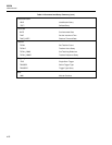
Table 4-2. Event Status Register (ESR)
Bit Name Description
0 OPC Operation Complete. set true (1) upon execution of the *OPC
command, indicating that the instrument has completed all selected
pending operations
1 not used Always set to 0.
2 QYE Query Error. Sets the QYE bit of the ESR. Example would be *IDN?;
*ESR? (vs. *ESR?; *IDN?). This causes the “?>“ prompt to be
returned.
3 DDE Device Dependent Error. Generated true (1) by overflows of the RS-
232 input buffer or by calibration errors. This causes the “!>“ prompt
to be returned.
4 EXE Execution Error. Generated true (logic 1) by parameters out of
bounds or by a valid command that could not be processed due to
an internal condition (such as calibration commands being received
when calibration is not enabled). This causes the “!>“ prompt to be
returned.
5 CME Generated true (1) by syntax errors, including: unrecognized
command and incorrect command sequences. This causes the "?>"
prompt to be returned.
6 not used Always set to 0
7 PON Power Transition. Set true (logic 1) after an off-to-on transition has
occurred in the instrument’s power supply.
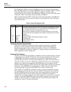
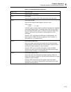
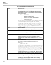
Status Byte Register (STB)
The inputs to the Status Byte Register (STB) include the Instrument Event Bit, Event
Status Bit, and Message Available Bit. In addition, the STB register generates a Master
Summary Status. Each input is described in Table 4-3. The output byte (except for bit 6)
is ANDed with the output byte of the corresponding Service Request Enable Register
(SRE). When there is a logic high correlation between any of the bits of the STB and
SRE registers, the associated Logical OR gate will output a logic high that is used as a
Master Summary Status (MSS) bit.