Front Panel Operations
Configuring a Measurement Channel
2
2-13
Configuring a Channel to Measure Temperature
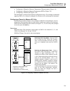
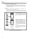
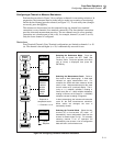
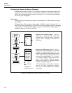
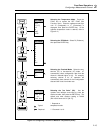
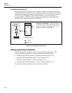
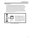
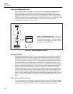
Perform the procedure in Figure 2-8 to configure a channel for measuring temperature
with thermocouples, or Figure 2-9 to measure temperature with resistance-temperature
detectors (RTDs). In preparation, the instrument must be in the inactive mode (not
scanning or monitoring) and the desired channel must be selected (see Figure 2-3). To
exit at any time (changes not saved), press the C key. The temperature scale, ºC or ºF,
is set by the Temperature-Toggle Power-On procedure (see Figure 2-2). When under
computer control, an open thermocouple default can be set by the TEMP_CONFIG
command.
Thermocouples
Thermocouples are formed by joining two wires of dissimilar metals, which produce a
voltage proportional to the temperature of the wire junction. The instrument conditions
this voltage into temperature measurements. Voltage conditioning includes
compensation for the type of thermocouple used and measurement-process
compensation that uses a reference temperature sensor built into the Input Module
(channels 1 to 20). The front panel terminals (channel 0) cannot be used for
thermocouples. The instrument supports nine standard thermocouples, each identified
with an American National Standards Institute (ANSI) alpha character (except [ ]): J,
[C], B, S, R, N, T, E, or K. A thermocouple type is selected as part of the channel
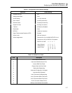
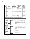
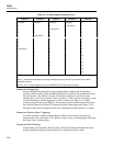
configuration. Table 2-3 summarizes the ranges and characteristics of the supported
thermocouples. The instrument displays "otc" when an open thermocouple is detected
(as selected with the TEMP_CONFIG command - see Chapter 4). A type "T"
thermocouple is supplied with the instrument.
Resistance-Temperature Detectors
Resistance-Temperature Detectors (RTDs) are formed from coils or strips of metal,
usually platinum, the resistance of which varies with temperature. The instrument
conditions this resistance into temperature measurements. The instrument supports any
platinum RTD that is calibrated to the IEC 751 Standard (a=0.00385 ohms/ohm/ºC).
RTDs are characterized by their resistance at 0 ºC, which is called the "ice point" or R0.
The most common R0 is 100 ohms. The instrument supports any IEC 751 Platinum RTD
with an R0 from 000.00 to 999.99, with a default of R0=100.00. Since RTDs are
resistance devices, they can be connected to the instrument using one channel (two-
terminal connection) or two channels (four-terminal connection). A four-channel
configuration provides increased measurement precision. Some RTDs can be purchased
in a four-terminal configuration, facilitating a four-terminal connection. The two
channels used in a four-terminal connection are a decade apart (n and n+10), for
example, channel 3 (n) and 13 (n+10). Only the lower channel is configured.
Thermocouple Restrictions:
Channel 0. Thermocouple measurements cannot use channel 0.
Open Thermocouple. The instrument displays OTC when an open thermocouple is
detected and ignores the channel while scanning.
Resistance Temperature Detectors Restrictions:
Four-Terminal Channels. Four-Terminal configurations are limited to channels 1 to 10
(n). The channel a decade higher (n + 10) is automatically reserved for use.


