2635A
Users Manual
7-14
1211 13 14 15 16 17 18 19 20
21 345678910
SOURCE
(4-WIRE)
SENSE
(4-WIRE)
H L H LH LH LH LH LH LH LH LH L
H L H LH LH LH LH LH LH LH LH L
4-WIRE (4T) CONNECTION
DECADE
RESISTANCE
BOX
HYDRA
INPUT
MODULE
op65f.eps
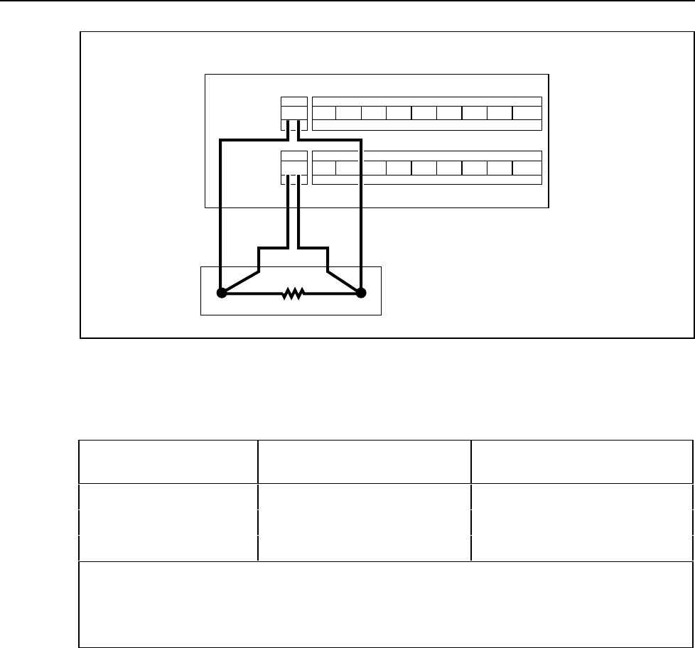
Figure 7-3. Four-Terminal Connections to Decade Resistance Box
Table 7-5. Performance Tests for RTD Temperature Function (Resistance Source) (DIN/IEC 751
Amendment 2) (ITS-90)
DECADE RESISTANCE
SOURCE
TEMPERATURE SIMULATED
°C
TEMPERATURE ACCURACY
1 YEAR @ 18-28°C
100 e 0 ± 0.12°C
200 e 266.35 ± 0.22°C
300 e 557.69 ± 0.37°C
These figures assume that RTD R0 is set to 100.00 ohms for each channel.
Accuracy given is for 4-wire measurements only. For 2-wire measurements, degrade the accuracy
specifications by 5.2 °C per ohm of single lead wire resistance. For 2-wire measurements, degrade the
accuracy by an additional 11°C (channels 1 .. 20)or 0.05°C (channel 0).
RTD Temperature Accuracy Test (Using DIN/IEC 751 RTD)
1. Switch OFF power to the instrument and disconnect all other high voltage inputs.
2. Remove the Input Module from the rear of the instrument. Open the Input Module
and connect a Platinum RTD, conforming to the European Standards IEC 751 (DIN
43760).
Two-terminal RTD: Connect the RTD’s excitation leads to the H (high) and L (low)
terminals of channel 1.
Four-terminal RTD: Connect the RTD’s excitation leads (one red and one black
wire) to the H (high) and L (low) terminals of channel 1. Connect the RTD’s second
pair of red and black leads to the H and L leads of channel 11. (Refer to Figure 7-3
for proper connection.) Reinstall the Input Module into the instrument.
