


Modem Operations
Summary of Modem Operations
6
6-3
Summary of Modem Operations
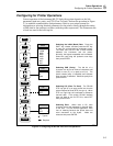
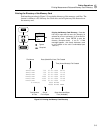
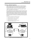
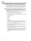
Modem operations allow an RS-232 connection between an instrument and a PC via
modems and telephone lines, instead of a direct RS-232 connection as described in
Chapter 4, "Computer Operations." Due to the wide variety of modems available and
their corresponding software, only the most common connection using a Hayes-
compatible modem using the AT command set is described. This connection can be
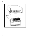
adapted to any configuration, following the basic rules in each procedure. A typical
overall connection diagram is shown in Figure 6-1.
Hayes-compatible modems are both configured and controlled by commands from a PC.
Since the Data Bucket does not have the capability to configure a modem, the modem is
configured using a PC, then the PC is removed and the modem is connected to the Data
Bucket. The modem operates in a simple answer mode since calls are never originated
from the instrument. The modem configuration is stored in the modem memory. Some
modems use an internal battery to prevent the erasure of the configuration if the modem
power switch is turned off, while others lose all configuration when the power is turned
off. Check the manual for your modem for an understanding of how the configuration is
maintained.
The information in this chapter is provided in five parts:
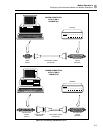
• Connecting the Modem to a PC for Configuration
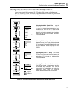
• Configuring the Modem for Modem Operations
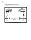
• Connecting the Modem to an Instrument
• Configuring the Instrument for Modem Operations
• Testing the RS-232/Modem Interface
MODEM
HS AA CD OH RD TD TR MR
HS AA CD OH RD TD TR MR
HYDRA
DATA BUCKET
300V
MAX
COM
V
FUNC ALRM
Mx+B
CANCEL
ENTER
RATE
INTVL FILES REVIEW
SHIFT LIST TOTAL
SINGLE
TRIGS
SCAN
MON
CLOCK MODE CLEAR
LOCAL COMM ZERO
mA
mVDCAC
k
Hz
REVIEW
LAST
CH
BUSYBATT
TELEPHONE LINES
RS-232 RS-232
PC
HYDRA
MODEM
op59f.eps
Figure 6-1. Overall PC-to-Instrument Modem Connection