


4-30 5708009-C
Advanced Energy
®
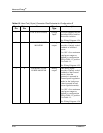
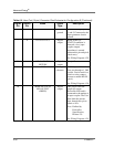
6 SIGNAL COMMON Chassis
ground
Common for signal pins 2,
3, and 5. Connected to the
Apex generator chassis
ground.
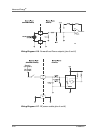
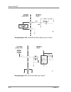
78 RF ON STATUS Digital
output
When an RF ON
STATUS condition is
detected, a low (opto-
coupler output)
impedance is created
between this pin and pin 8
(6mA max).
See Wiring Diagram 4-29.
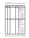
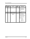
8 RF ON STATUS
RETURN
Digital
output
See pin 7
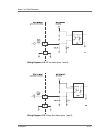
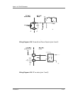
9 +15 Vdc Voltage
reference
+15 Vdc provided to the
User port through a 1.1k
Ω
resistor. Can be used for a
switch or relay contact
closure to enable RF ON
(pin 4).
See Wiring Diagram 4-30.
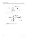
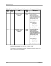
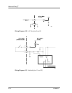
10 MODULE STATUS
LED OUTPUT
(GREEN)
Digital
output
This pin provides the
output for remote
DeviceNet LED and is
connected to the emitter of
an opto-coupler. The User
must limit the current
draw through this pin to
45mA or less.
Note: Defined by
DeviceNet
Specification,
Release 2.0
See Wiring Diagram 4-24.
Table 4-3. User Port (15-pin) Connector Pins Exclusive for Configuration E (Continued)
Signal
Pin
Return
Pin
Name Signal
Type
Description