


5708009-C 4-1
Chapter
Apex 1 to 5.5 kW Generator
Chapter
4
4Interfaces and Indicators
This chapter contains information on the Apex communication interfaces and status
indicators (LEDs). It also contains representative drawings of the front and rear panels
of the unit. The chapter is divided up into sections as follows.
• The first section of the chapter, “Apex User Port Options” on page 4-2, contains
a subsection for each of the User port options available with the Apex 1 to 5.5 kW
generator. These subsections are:
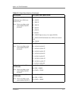
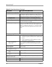
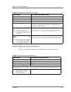
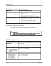
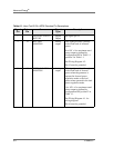
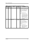
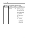
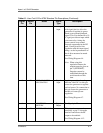
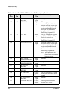
–“25-Pin Apex Standard User Port” on page 4-2
–“15-Pin User Port (Exclusive—Option D)” on page 4-16
–“15-Pin User Port (Exclusive—Option E)” on page 4-26
• The second section of the chapter, “Apex Host Port Options” on page 4-37,
contains a subsection for each of the serial Host port options available with the
Apex 1 to 5.5 kW generator. These subsections are:
–“Host Port—RS-232 With AE Bus” on page 4-37
–“Host Port—Profibus” on page 4-58
–“Host Port—DeviceNet” on page 4-72
• The third section of the chapter, “Apex Status Indicators (LEDs)” on page 4-79,
contains information on interpreting the LED indicators that appear on some Apex
units.
• The final section of the chapter, “Apex Panel Illustrations” on page 4-80, provides
illustrations of Apex front and rear panels.
Not all of these sections apply to any one Apex unit. To identify the sections that
apply to your unit, see “Using this Manual to Find Information for Your Generator”
on page 1-1. Each of the option-specific sections of this chapter also contain PIN
configuration notes, which help you confirm whether or not a particular section
applies to your unit.