


5708009-C 4-17
Apex 1 to 5.5 kW Generator
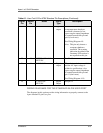
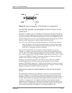
Figure 4-2. User port connector 15 Pin Exclusive for configuration D
SATISFYING MINIMAL REQUIREMENTS FOR OPTION D 15-PIN
USER PORT
Regardless of whether you are controlling and monitoring the generator through the
User port or through another port, two User port signals must be satisfied for the Apex
unit to be operational: RF POWER ENABLE (pins 4 and 9) and INTERLOCK (pins 11
and 6). In other words, even if you are controlling the generator through the serial port
interface, the RF signal must be enabled and the interlock satisfied.
Note: If you are controlling your generator through a port other than the User port,
make sure that the control mode is set appropriately (to host mode to control
through the Host port, for example) before powering up the unit. The control
mode can be set through a Host port command.
If you are not using the User port to control or monitor the unit, you can use a
“dummy” or “cheater” plug to satisfy these two signals, thereby ignoring the User
port. To make such a plug, solder two jumpers on a mating connector: one between
pins 4 and 9 to satisfy the RF POWER ENABLE signal and one between pins 11 and 6
to satisfy the INTERLOCK signal. To determine the physical location of these pin
numbers on the User port, see Figure 4-2 on page 4-17.
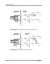
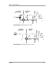
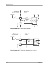
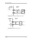
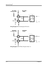
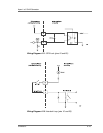
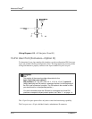
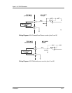
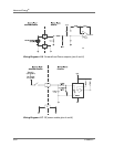
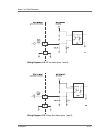
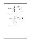
If desired, you can add an emergency off switch in series with the RF POWER
ENABLE signal (pins 4 and 9) or tie your system interlocks in series with the
generator INTERLOCK signal (pins 11 and 6) by following the connections for those
pins described in “Pin Descriptions for Option D User Port” on page 4-18 and “Wiring
Diagrams for Option D 15-Pin User Port” on page 4-20.
INTERFACE CABLING REQUIREMENTS FOR OPTION D USER
PORT
The cable used to connect the Apex generator’s User port to the system controller
must be a shielded, 15-wire I/O cable. Twisted-pair wiring may be used but is not
mandatory. Signal losses should be minimized by keeping the cable length as short as
possible. The maximum recommended cable length between the generator and the
controller is 10 meters (33´). To minimize interference from adjacent electrical
equipment, the EMI shield in the cable must be terminated to the metal shells of the
cable’s connectors. Additionally, the chassis of the Apex generator must be tied to a
local earth ground through an adequately sized copper grounding strap.