


5708009-C 4-29
Apex 1 to 5.5 kW Generator
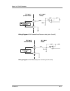
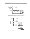
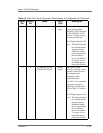
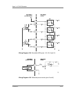
4 RF POWER ENABLE Digital
input
This pin represents RF
output being enabled
when a 4 to 30V input (pin
9, RF ON BIAS, can be
used as a voltage source)
is present on this pin.
See Wiring Diagram 4-27.
Note: The interlocks must
be satisfied and the
setpoint must be
within the Output
power range before
unit will deliver
power. See Table 3-
3. on page 3-6 for
the Output power
range specification.
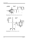
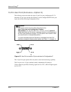
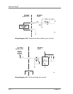
56FORWARD / LOAD
POWER SETPOINT
Analog
input
This analog signal
provides a linearly scaled
control of the forward or
load output power
depending on the
regulation mode.
0 to 10V = 0 to maximum
rated power output as
defined by configuration
PIN in Table 1-1 position
2.
See Wiring Diagram 4-28.
Note: The interlocks must
be satisfied and the
setpoint must be
within the Output
power range before
unit will deliver
power. See Table 3-
3. on page 3-6 for
the Output power
range specification.
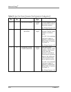
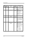
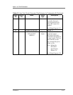
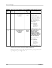
Table 4-3. User Port (15-pin) Connector Pins Exclusive for Configuration E (Continued)
Signal
Pin
Return
Pin
Name Signal
Type
Description