


5708009-C 2-3
Apex 1 to 5.5 kW Generator
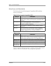
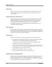
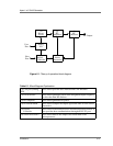
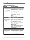
Figure 2-1. Theory of operation block diagram
Analog
I/O
Driver/
Exciter
RF
Amplifiers
Digital
Controller
Sensor
Electronics
(1)
(2)
(3)
(5)
(6)
User
RF
Measure
(4)
RF Output
Host
Port
Port
Table 2-1. Block Diagram Explanation
(1) User port (Analog
I/O)
This section provides user interface and CEX functions.
(2) Driver/Exciter This section generates power at the designated output frequency
to drive the main RF sections.
(3) RF Amplifier This section generates RF power.
(4) RF Measurement This section samples the output signal and sends it to the sensor
electronics.
(5) Digital
Controller
This section is the main processor and data acquisition section. It
also provides host communications through an RS-232 port.
(6) Sensor Electronics This section detects RF samples and sends them to the
microprocessor.