


5708009-C 4-77
Apex 1 to 5.5 kW Generator
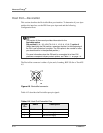
DeviceNet is connected through pins 1, 10, 13, 14, and 15 of the User port (See table
4-1).
When the generator powers up, it defaults to user control mode. However, engaging
DeviceNet automatically places the generator in host control mode. Note that when
the generator is in host control mode, the regulation mode is forward power.
Before operating your Apex generator through the DeviceNet port, ensure that your
network is connected to the DeviceNet port and the User port. Also, ensure that you
have selected an appropriate MAC ID and baud rate. Finally, ensure that you have
read the following information about command and response messages and the
DeviceNet LEDs.
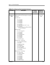
DeviceNet Poll Command Message
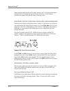
Note that this device uses DeviceNet’s Group 2 I/O Poll Command message (and the
associated Group 1 I/O Poll Response message) to transfer low-level I/O data between
the device (slave) and the master. Table 4-16 represents the structure of the poll
command message.
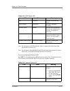
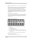
Power Output Setpoint 0 to 10 V; 10 V = full output power of the power supply
PO = Power On
1 = turns power supply’s output ON
0 = turns power supply OFF
Note: The 16-bit AI should be shifted right four bits and the remaining first four bits
should be filled with 0s. This changes the 16-bit AI to a 12-bit AI with a value
of 10 V = OFFF
hex
.
Note: Power Output Setpoint values exceeding OFFF
hex
are limited to OFFF
hex
.
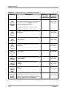
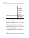
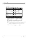
DeviceNet Response Message
Table 4-17 represents the structure of the response message.
Table 4-16. Poll Command Message
Byte Bit 7 Bit 6 Bit 5 Bit 4 Bit 3 Bit 2 Bit 1 Bit 0
0 Power Output Setpoint AI (LSB)
10000Power Output Setpoint AI
(MSB)
200000000
300000000
4PO