


4-8 5708009-C
Advanced Energy
®
11 DC BUS OK
RETURN
Digital
Output
See Signal Pin 24
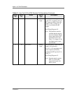
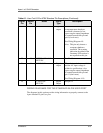
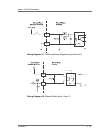
12 25 CEX LOCK Digital
output
When the generator is
successfully phase-locked to an
external oscillator, a low (opto-
coupler output) impedance is
created between this pin and
return pin 25. (6 mA max)
See Wiring Diagram 4-11.
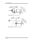
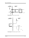
13 21 +15 VDC Analog
output
This pin, referenced to ground,
provides a +15 Vdc auxiliary
supply for external use.
See Wiring Diagram 4-13.
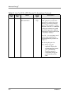
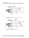
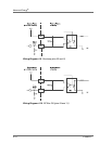
14 1 SETPOINT STATUS Digital
output
When the output is equal to the
requested setpoint, a low (opto-
coupler output) impedance is
created between this pin and
pin 1. (6 mA max).
See Wiring Diagram 4-8.
Note: This condition is also
referred to as the generator
being at setpoint.
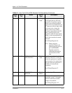
15 RFL POWER
MONITOR RETURN
Analog
output
See pin 2
16 FWD/LOAD PWR
MONITOR RETURN
Analog
output
See pin 3
17 RF PWR ON
RETURN
Digital
input
See pin 4
18 SETPOINT
RETURN
Analog
input
See pin 5
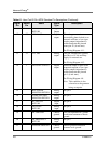
19 DC GROUND Chassis
ground
This pin represents DC ground
connection common to chassis
ground.
20 DC BIAS INPUT
RETURN
Analog
input
See pin 7
21 CHASSIS GROUND Chassis
ground
Chassis ground connection
common to dc ground
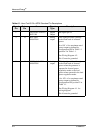
Table 4-1. User Port 25-Pin APEX Standard Pin Descriptions (Continued)
Signal
Pin
Return
Pin
Name Signal
Type
Description