


5708009-C 4-79
Apex 1 to 5.5 kW Generator
APEX STATUS INDICATORS (LEDS)
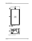
Some Apex generators provide the following status indicators on the front or rear
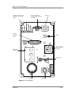
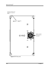
panel. For panel illustrations, see “Apex Panel Illustrations” on page 4-80.
This section of the manual provides information for the:
Passive digital display option
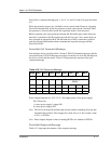
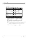
PIN position 5, (A 1 2 3 4 5 6 7 8 9 10 11 12 13 14 15 16 17) option 2.
(When identifying the PIN position, remember that the A at the beginning of
the PIN is not counted as a position. The PIN option is the number or letter
you should look for in the specified position.)
For more information about the PIN and for a complete list of how PIN
positions correspond to Apex product options, see Table 1-1. on page 1-4.
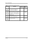
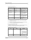
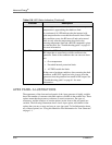
Table 4-18. LED Status Indicators
Indicator Description
AC ON This green LED indicates that ac power is available within
the generator and all three phases are present.
RF ON This green LED indicates that RF power is on (enabled).
Depending on the selected setpoint value, RF power may
or may not be present at the output connector.
A flashing LED indicates an error. See “Troubleshooting
guide” on page 6-1.
INTERLOCK When lit this green LED indicates that the required
interlock criteria has been satisfied. The interlock must be
satisfied before the output can be enabled. The LED
remains on as long as the interlock loop is satisfied. If you
suspect an error and this LED is off, see “Troubleshooting
guide” on page 6-1.
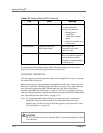
POWER LIMIT When lit, this yellow LED indicates that the generator is
unable to supply the requested power level due to a
limiting condition in the generator. Power limits do not
disable the RF output of the generator. If you suspect an
error and this LED is lit, see “Troubleshooting guide” on
page 6-1.