


4-16 5708009-C
Advanced Energy
®
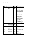
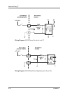
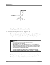
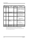
Wiring Diagram 4-13. +15 Vdc (pins 13 and 21)
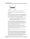
15-Pin User Port (Exclusive—Option D)
To determine if your Apex unit has this interface, use the configuration PIN from your
Apex unit and the following Configuration Note. The diagrams in this section provide
wiring information to properly connect to the Apex standard 25-pin User port.
This 15-pin User port option offers only basic control and monitoring capability.
The User port uses a 15-pin, shielded, female, subminiature-D connector.
This section of the manual provides information for the:
Apex 15-pin User port, option D
PIN position 8, (A 1 2 3 4 5 6 7 8 9 10 11 12 13 14 15 16 17) option D.
(When identifying the PIN position, remember that the A at the beginning of
the PIN is not counted as a position. The PIN option is the number or letter
you should look for in the specified position.)
For more information about the PIN and for a complete list of how PIN
positions correspond to Apex product options, see Table 1-1. on page 1-4.