


5708009-C 4-7
Apex 1 to 5.5 kW Generator
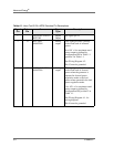
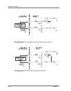
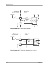
720DC BIAS INPUT Analog
input
This pin is used in conjunction
with signal pin 6 to allow the
generator to regulate its power
based on an external feedback
signal. This User defined 0 to 10
V signal provides an input which
you can use for closing the
power control loop around
external components in the RF
path. Usually used for bias
regulation with this input signal
being a scaled representation of
the dc bias measured at match
network.
See Wiring Diagram 4-4.
Note: When using this
regulation feature, the
setpoint must be given at
pin 5 (SETPOINT).
Setpoints cannot be
established through the
serial interface at this
time.
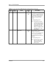
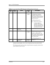
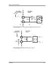
821FWD/LOAD PWR
REGULATION
Digital
input
Applying a positive dc voltage
between 4 and 30 V to this pin
causes the generator to regulate
on load power. No connection to
this pin causes the generator to
default to forward power
regulation.
See Wiring Diagram 4-7.
9 OVERTEMP
RETURN
Digital
Output
See Signal pin 22
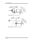
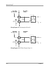
10 23 INTERLOCK LOOP This pin when connected
externally to pin 23 closes the
interlock and allows the RF
output to be enabled.
See Wiring Diagram 4-12.
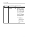
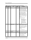
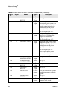
Table 4-1. User Port 25-Pin APEX Standard Pin Descriptions (Continued)
Signal
Pin
Return
Pin
Name Signal
Type
Description