


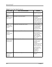

6-6 5708009-C
Advanced Energy
®
External Load Checks - Open/Short RF Output Path
Use extreme caution as this section is involves troubleshooting the output of the unit.
There are 4 basic components that could impede the RF path: the Apex unit output
connector, the output cable, the tuner, or the chamber. Follow the steps below.
1. Turn the rear circuit breaker off to ensure that there is no RF power at the output
of the unit.
2. For the Apex output connector
a. Remove the output cable and visually inspect the output connector for signs of
arcing or heat stress.
b. Verify an open is measured between the center conductor and outer shield.
c. Make sure the output connector is mounted firmly to the chassis.
3. For the output cable
a. Visually make sure there is a good connection between the output cable and
end connectors on both sides of the output cable.
b. Verify the continuity of the center conductor.
c. Verify the continuity of the outer shield.
d. Verify that there is no continuity between the center conductors and outer
shields.
e. Swap cables if possible and retry operating the Apex.
4. For the tuner and the chamber
The only way to truly isolate the tuner or the chamber is to swap the tuner or the
Apex unit with another known good unit. You can also run the unit into a 50
Ω
dummy load and follow the steps in “Troubleshooting guide” on page 6-1.
Also consider these questions:
1. Are you currently setting up a new chamber system?
2. Has any work been done recently on the chamber?
3. Have there been any changes in your process recently?
4. Is your reflected power readings close to the Apex reflected power limit? See
“Electrical Specifications” on page 3-5.
Use suitable precautions; this area contains high voltages that could
cause serious injury or death.