


5708009-C 4-5
Apex 1 to 5.5 kW Generator
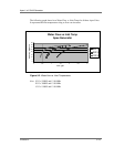
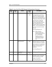
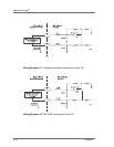
417RF PWR ON Digital
input
When a positive voltage between
4 and 30 V is applied to this pin
RF output is enabled. Once the
output is ON, a voltage of 1.5
Vdc or less disables the RF
output.
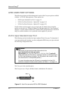
See Wiring Diagram 4-5.
Note: The interlocks must be
satisfied and the setpoint
must be within the Output
power range before unit
will deliver power. See
Table 3-3. on page 3-6 for
the Output power range
specification.
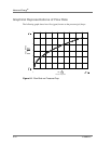
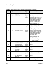
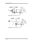
518SETPOINT Analog
input
This pin linearly controls the RF
output of the generator.
0 to 10V = 0 to maximum rated
power output as defined by
configuration PIN position 2 in
Table 1-1.
See Wiring Diagram 4-3.
Note: Setpoint must be greater
than 1% of full rated
output before unit will
deliver power.
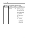
Table 4-1. User Port 25-Pin APEX Standard Pin Descriptions (Continued)
Signal
Pin
Return
Pin
Name Signal
Type
Description