


5708009-C 4-9
Apex 1 to 5.5 kW Generator
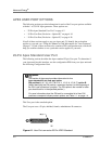
WIRING DIAGRAMS FOR THE STANDARD 25-PIN USER PORT
The diagrams in this section provide wiring information to properly connect to the
Apex standard 25-pin User port.
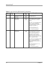
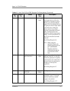
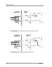
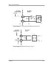
22 9 OVERTEMP Digital
output
When an internal
overtemperature shutdown
condition is detected, a low
(opto-coupler output) impedance
is created between this pin and
pin 9 (6 mA max).
See Wiring Diagram 4-9.
Note: This pin only detects a
overtemp shutdown
condition. The warning
indication described in the
Overtemp LED section is
not reported on this pin.
23 10 INTERLOCK LOOP
RETURN
See Pin 10.
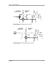
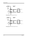
24 11 DC BUS OK Digital
output
When the interlocks are satisfied
and the AC input voltage is
within its specification, a low
(opto-coupler output) impedance
is created between this pin and
pin 11 (6mA max).
See Wiring Diagram 4-10.
25 CEX LOCK
RETURN
Digital
Output
See pin 12
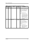
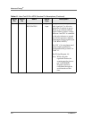
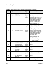
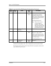
Table 4-1. User Port 25-Pin APEX Standard Pin Descriptions (Continued)
Signal
Pin
Return
Pin
Name Signal
Type
Description