


5708009-C 4-73
Apex 1 to 5.5 kW Generator
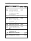
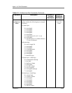
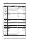
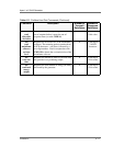
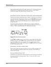
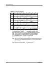
Analog inputs and outputs use the values and equations listed in Table 4-13 to define
the voltage ranges and the corresponding digital values (assuming N is the number of
bits of resolution available at the DeviceNet interface). Unsigned binary is used to
represent the 0 to +10 V range.
Note: The conversion is assumed to be linear across the range (a one-bit change
always corresponds to the same voltage change in the AI/AO within the
hardware capabilities of the device).
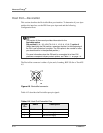
DEVICENET INTERFACE CHARACTERISTICS
The device uses rotary switches to set the MAC ID. This allows you to visually verify
the MAC ID setting, and simplifies the configuration of replacement parts in field
repair situations.
The device is delivered with the baud rate set to 500 KBd which does not change if the
device is power-cycled.
The device supports the DeviceNet Duplicate MAC ID Check protocol.
The device uses DeviceNet’s Group 2 I/O Poll Command message (and the associated
Group 1 I/O Poll Response message) to transfer low-level I/O data between the device
(slave) and the master.
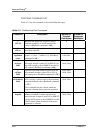
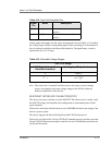
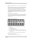
4 CAN_H DeviceNet data transmit/
receive
5 CAN_L DeviceNet data transmit/
receive
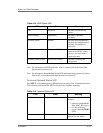
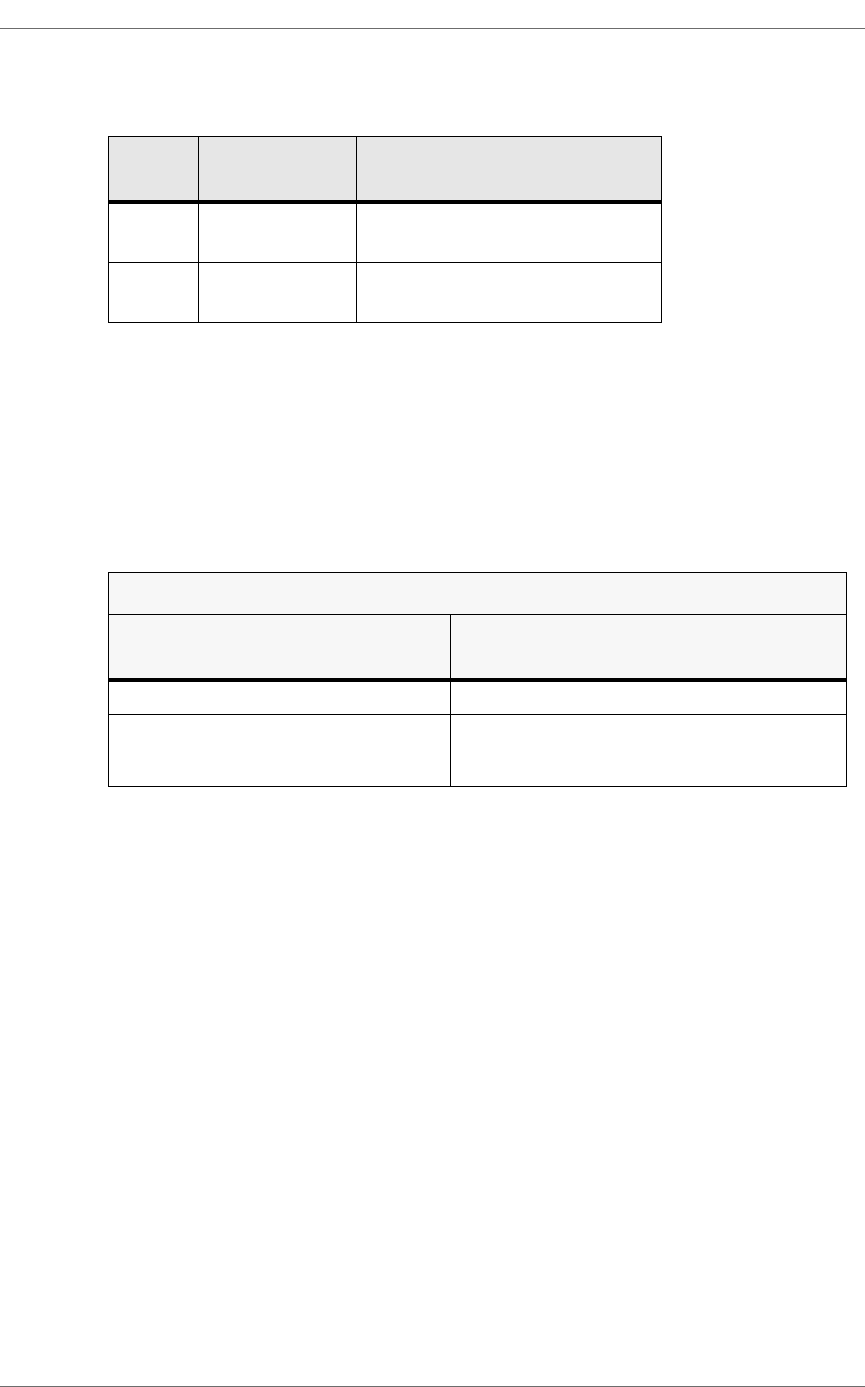
Table 4-13. DeviceNet Voltage Ranges
0 to +10 V Range
AI/AO Digital Value (at the
DeviceNet interface)
Analog Input/Output to device
0 0.000 V
Table 4-12. Host Port DeviceNet Pins
Signal
Pin
Name Description
2
N
1–
10V
2
N
1–
2
N
---------------
×