


4-20 5708009-C
Advanced Energy
®
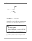
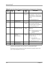
WIRING DIAGRAMS FOR OPTION D 15-PIN USER PORT
The diagrams in this section provide wiring information to properly connect to the
Apex 15-pin configuration D User port.
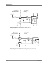
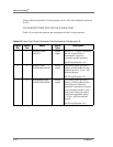
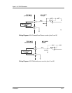
96RF ON BIAS Voltage
reference
+15 Vdc provided to the User
port through a 1.1 k
Ω resistor. It
can be used for a switch or relay
contact closure to enable RF ON
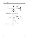
(pin 4).
See Wiring Diagram 4-21.
10 UNASSIGNED
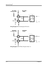
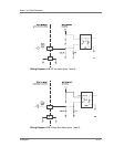
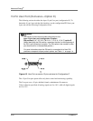
11 6 INTERLOCK Analog
Input
When connected together, these
pins close the interlock and
allows RF output to be enabled.
See Wiring Diagram 4-23.
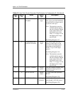
12 6 RESERVED for
PULSING ENABLE
Digital
Input
This pin is currently reserved for
future use.
Note: Pulsing parameters are set
via the digital/serial
interface.
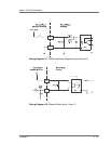
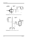
13 6 FWD/LOAD
POWER
REGULATION
Digital
Input
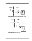
Load Power Regulation is
enabled when a 4 to 30V input is
present on this pin.
Note: Forward Power
Regulation is the default.
See Wiring Diagram 4-22.
14 UNASSIGNED
15 UNASSIGNED
Table 4-2. User Port (15-pin) Connector Pins Exclusive for Configuration D (Continued)
Signal
Pin
Return
Pin
Name Signal
Type
Description