


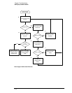
Chapter 5: Troubleshooting
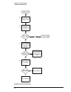
To check probe power outputs
5–16
To check probe power outputs
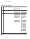
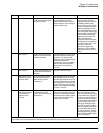
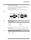
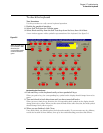
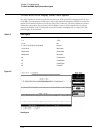
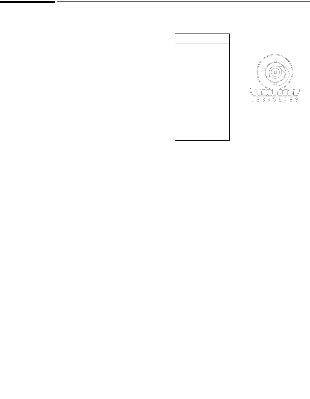
Probe power outputs are on the front panel, surrounding each BNC input.
Any failure may be a problem with the probe power and control assembly, the AutoProbe flex
cable W13, or the probe power and control cable W12.
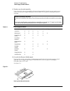
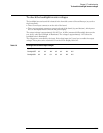
Use the table and figure to the right
to check the power output at the
connectors.
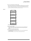
The +12 V and –12 V supplies
come directly from the power
supply, and the +3 V and –3 V
supplies are developed in
three-terminal regulators on
the probe power & control
assembly.
Measure the voltages with respect
to the ground terminal on the front
panel, located near the Aux Out
BNC.
Do not attempt to measure voltages
at pins 3 through 7.
Pin Supply
1+3V
2 –3V
3 Offset
4Data
5 &
ring
Probe ID
6Clk
7R
p
8 –12 V
9 +12 V