


Chapter 8: Theory of Operation
Acquisition Theory
8–8
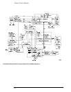
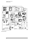
Trigger There are four main trigger circuits: Trigger Conditioning, Analog Comparators, a
Trigger Multiplexer, and Logic Trigger. Trigger signals from the channel are fed to the analog
trigger comparators and the trigger conditioning circuit. The trigger conditioning circuitry
selects dc, ac, low-frequency reject, high-frequency reject, and noise reject (hysteresis)
modes and sets the trigger levels. The trigger multiplexer selects the trigger modes, such as
edge, glitch, and pattern trigger.
The channel triggers are sent to the Logic Trigger. The logic trigger provides the advanced
triggering functions, such as holdoff, delay, and pattern duration and range. The data delay and
clock delay timers are used to implement trigger functions that require timing between 1.5 and
20 ns.
The auxiliary trigger, which cannot be displayed on screen, is compared to the trigger level setting
in a separate circuit. The line sync trigger line from the power supply is combined in a multiplexer
with the TV trigger and the high frequency reject comparators before being sent to the analog
trigger.
Time Base The time base provides the sample clocks and timing necessary for data
acquisition. It primarily consists of a reference oscillator, time base IC, and trigger
interpolator pulse stretcher.
• The 100-MHz oscillator provides the timebase reference.
• The time base has programmable dividers to provide the rest of the sample frequencies
appropriate for the time range selected. The time base uses the time-stretched output of the
interpolator pulse stretcher to time-reference the sampling to the trigger point. The time base
has counters to control how much data is taken after the trigger event (post-trigger data).
After enough pre-trigger samples have occurred, the time base IC sends a signal to the trigger
multiplexer (ARM) indicating it is ready for the trigger event. When the trigger condition is
satisfied, the trigger multiplexer sends a signal back to the time base (SYSTRIG). The time
base IC then starts the post-trigger delay counter. When the countdown reaches zero, the
sample clocks are stopped and the CPU is signaled that the acquisition is complete.
• The Interpolator Pulse Stretcher is a dual-slope integrator that acts as a time-interval stretcher.
When the trigger system receives a signal that meets the programmed triggering requirements
(SYSTRIG), it signals the time base. The time base then sends a pulse to the pulse stretcher.
The pulse is equal in width to the time between the trigger (SYSTRIG) and the next sample
clock. The pulse stretcher stretches this time by a factor of approximately 1000. Meanwhile,
the time base hybrid runs a counter with a clock derived from the sample rate oscillator. When
the interpolator indicates the stretch is complete, the counter is stopped. The count
represents, with high accuracy, the time between the trigger and the first sample clock. The
count is stored and used to place the recently acquired data in relationship to the trigger point.
Calibration The Calibration circuit provides several signals to the Probe Compensation and
Aux Out outputs. Which signal is driven to the front panel depends on the current selection
from the drop-down menu in the Calibration dialog box. Available signals for Aux Out include
a 715 Hz probe compensation signal, a pulse representing the trigger event, the timebase
clock, or a dc voltage in the range –2.5 to +2.5 V. The dc voltage is used for self-calibration,
and is an output from a 16-channel DAC. The calibration signals are sent to an analog
multiplexer, which selects the signal that will be sent to the front panel.
Microprocessor Interface The Microprocessor Interface provides control and interface
between the system control and digital functions in the acquisition circuitry.