


Chapter 6: Replacing Assemblies
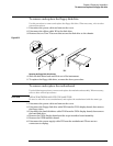
To remove and replace the scope interface board and SVGA display board
6–17
To remove and replace the scope interface board and SVGA display board
Use these steps to remove and replace the scope interface board and SVGA display boards. These
boards must be removed and replaced as a unit. When necessary, refer to other removal
procedures.
1
Disconnect the power cable and remove the cover.
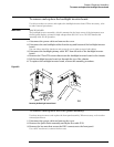
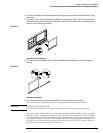
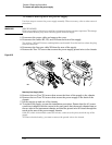
2 Disconnect these cables from the scope interface board:
• Acquisition cable W11
• Keyboard cable W16
3
Disconnect these cables from the SVGA display board:
• Display board to floppy cable W8
• Display board to hard drive cable W10
• Motherboard floppy cable W7
• Motherboard hard drive cable W9
• Backlight primary cable W17
• Display video cable W20
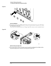
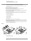
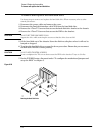
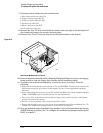
4
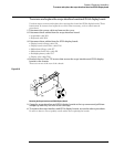
Remove the two Torx T15 screws that secure the scope interface and SVGA display
boards to the chassis.
These screws are at the rear of the chassis.
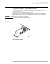
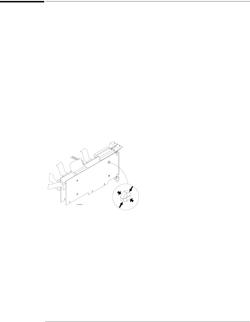
Figure 6-19
Removing the Scope Interface and SVGA Display Boards
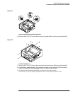
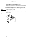
5 Grasp the scope interface and SVGA display boards at the top corners and pull them
straight up until they are free of the card cage.
6 To replace the scope interface and SVGA display boards, reverse the above procedure.
Be sure to observe correct polarity on all cables when replacing the boards.