


Chapter 4: Calibrating and Adjusting
To check the power supply
4–5
4
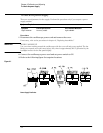
Connect the common lead of the voltmeter to the GND test point.
5 Connect the positive lead of the voltmeter to the +5.1 V test point.
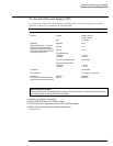
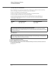
6 Verify that the +5.1 supply voltage is within limits as shown in the following table:
Table 4-1 Power Supply Voltage Limits
7
Repeat steps 4 through 6 for each of the other supply voltages.
If any supply voltage is not within specifications, see chapter 5, “Troubleshooting.”
Supply Voltage Specification Limits
+5.1 V ± 0.1 V +5.0 V to +5.2 V
-5.2 V ± 0.1 V -5.1 V to -5.3 V
+12.2 V ± 0.3 V +11.9 V to +12.5 V
-12.2 V ± 0.3 V -11.9 V to -12.5 V
+15 V bias +14 V to +16 V