


Chapter 8: Theory of Operation
Acquisition Theory
8–9
Analog Interface The Analog Interface provides analog control of functions in the
acquisition circuitry. It is primarily DACs with accurate references and filtered outputs. The
analog interface controls:
• Channel offsets
• Trigger levels
• Two logic trigger functions
Acquisition Modes
The Agilent Technologies 54835A provides two acquisition modes:
• 2 GSa/s on each of the four channel inputs
• 4 GSa/s on channel 1 and channel 3 inputs
The Agilent Technologies 54845A provides two acquisition modes:
• 4 GSa/s on each of the four channel inputs
• 8 GSa/s on channel 1 and channel 3 inputs
4 GSa/s In this mode, the scope uses all four channel inputs. Each channel can sample up
to 4 GSa/s (for Agilent Technologies 54845A).
8 GSa/s In this mode, the scope only uses the channel 1 and channel 3 inputs. The ADC
hybrids for the channel 1 inputs are routed to both the channel 1 and channel 2 ADC hybrids.
The hybrids are time-aligned to sample 90° out-of-phase to yield a sample rate of 8 GSa/s.
Channel 3 and channel 4 are combined in the same way (for Agilent Technologies 54845A).
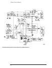
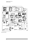
Scope Interface Board
The Scope Interface Board has three primary functions:
• Interface the acquisition board to the motherboard system controller.
• Manage the waveform display, through an interface to the SVGA display board.
• Implement miscellaneous oscilloscope functions, including an RS-232 interface to the front-
panel keyboard, a 32-bit timer, and non-volatile RAM.
Acquisition Board Interface The interface to the acquisition board consists of 16 data
lines, 10 address lines, a R/W line, and read and write strobes. A second read strobe is used
for reading acquisition data; the address latches are not used when this strobe is active.
Three lines are used to indicate run, trigger, and interpolator status; two control lines are
used for trigger control and clocking.
There are two address ranges on the acquisition board; the first is used for reading acquisition
data, while the second is used to access status and control elements of the board.
Waveform Display Management A PC video connector connects the scope interface
board to the SVGA display board. The scope interface board accepts video clock and
synchronization signals from the SVGA display board, and drives 16 bits of RGB data in 5,6,5
format to the display controller on the SVGA display board. The display driver will only
substitute the PC video RGB data from the scope interface card for the other video data
when the screen data matches the value specified in the display driver. In this way, the scope
interface card can supply the waveform data from the acquisition system and have it properly
multiplexed with regular video data for output on the flat-panel display.
Miscellaneous System Functions An RS-232 interface is used to communicate with the
front panel keyboard. The connector routes transmit and receive, power supply bias and
inhibit signals, and keyboard power to the keyboard. The interface functionality is contained
in the FPGA. The data rate is 19.2 KBaud, with 1 start bit, 8 data bits (LSB first), and one
stop bit, no parity. The keyboard itself has a controller that transmits and receives data
through this interface.
Non-Volatile RAM (NVRAM) on the scope interface board provides high-speed access to
instrument configuration settings.