


Chapter 3: Testing Performance
To test input resistance
3–6
To test input resistance
This test checks the input resistance of the vertical inputs. A four-wire measurement is used to
accurately measure the 50-
Ω and 1-MΩ inputs.
Specification: 1 M
Ω ±1% and 50 Ω ±1.5%
Equipment Required
Procedure
1
Set up the multimeter to make a four-wire resistance measurement.
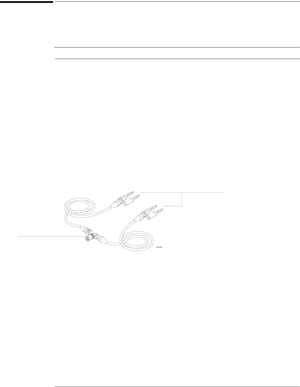
2 Assemble the test cables.
a Use the two BNC-to-banana adapters to connect one end of each BNC cable to the four-
wire resistance connections on the multimeter.
b Connect the free ends of the cables to the BNC tee.
See figure 3-3.
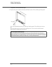
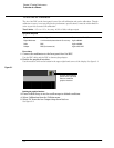
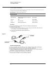
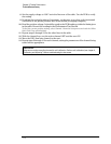
Figure 3-3
Input Resistance Equipment Setup
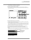
3 Connect the male end of the BNC tee to the channel 1 input of the oscilloscope.
4 Press Default Setup to set the oscilloscope to default conditions.
5 Press the Input key for Channel 1 to select 1 MΩ, then 50Ω, and verify resistance
readings of 1 M
Ω ±10 kΩ and 50 Ω ±0.75 Ω respectively.
6 Record the readings in the Performance Test Record.
7 Repeat steps 3 through 6 on the remaining channels.
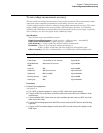
Equipment Critical Specifications Recommended Model/Part
Digital Multimeter Measure resistance (4-wire) at better than
0.25% accuracy
Agilent 34401A
Cables (2) BNC Agilent 10503A
Adapter BNC Tee (m)(f)(f) Agilent 1250-0781
Adapters (2) BNC (f) to dual banana (m) Agilent 1251-2277
To ohmmeter
4-wire inputs
To oscilloscope
channel input